
Installation Instructions
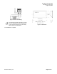
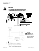
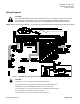
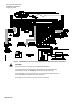
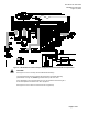
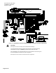
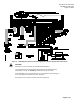
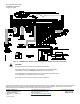
Table Of Contents

Document No. 546-14410
Installations Instructions
August 16, 2013
Information in this publication is based on current specifications believed correct at the time of publication. The right is reserved to make changes as
design improvements are introduced. APOGEE and Insight are registered trademarks of Siemens Industry. Other product or company names
mentioned herein may be the trademarks of their respective owners. © 2013 Siemens Industry, Inc.
Siemens Industry, Inc.
Building Technologies Division
1000 Deerfield Parkway
Buffalo Grove, IL 60089-4513
USA
1-847-215-1000
Your feedback is important to us. If you
have comments about this document,
please send them to
SBT_technical.editor.us.sbt@siemens.com
.
Document No. 546-14410
Printed in the USA
Page 10 of 10
Figure 12. LCM-OAVS Slow Actuation Damper Supply/Venturi Exhaust with BTU Compensation.
CAUTION:
See Figure 5 for how to correctly wire the Offboard Air Module(s).
The LCM-OAVS has two terminal blocks with terminations numbered identically
(terminations 1 through 16). DO NOT get these mixed up with each other.
If the LCM-OAVS is not connected as shown, it is not resistant to electrical surges. It
is also susceptible to interference from other equipment.
See Figure 6 for how to wire a 4-20 mA sensor at AI 4 (optional).