
Installation Instructions
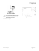
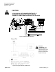
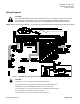
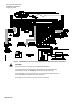
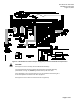
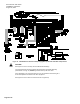
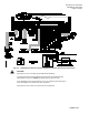
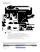
Table Of Contents

Document No. 546-14410
Installations Instructions
August 16, 2013
Page 2 of 10 Siemens Industry, Inc.
Expected Installation Time
New controller installation 10 Minutes
Replacement (old controller has removable
terminal blocks)
6 Minutes
Replacement (old controller does not have
removable terminal blocks)
16 Minutes
NOTE: You may require additional time for database
work at the field panel.
Required Tools and Materials
• 1/8-inch flat-blade screwdriver
• Small flat-blade screwdriver
• Cabling and connectors
• Cordless drill/driver set
Prerequisites
• Wiring conforms to NEC and local codes and
regulations. For further information, refer to the
Wiring Guidelines Manual (125-3002).
• 24 Vac Class II power source available.
• Supply power to the unit is OFF.
• Any application specific hardware or devices
installed.
• Room temperature sensor installed (optional).
A low-cost temporary RTS (P/N 540-658P25) is
available that plugs into the RTS port on the
LCM, providing temperature input and actual
space control until a permanent RTS is
installed.
If the controller is being installed on a box with 1
or more stages of electric heat, the 550-809 MOV
with pre-terminated spade connectors must be
installed across the manufacturer-supplied
airflow switch. MOVs can be installed at the time
the controller is factory mounted; coordinate with
the box manufacturer prior to order placement.
For field installation, see the Metal Oxide Varistor
Kit Installation Instructions (540-986).
Installation Instructions
All wiring must conform to all applicable national
and local codes and regulations (NEC, CE, etc).
1. Secure the mounting rail (Figure 1) in the
controller’s desired location.
2. Place the ESD wrist strap on your wrist and attach
it to a good earth ground.
3. Remove the controller from the static proof bag and
snap it into place on the mounting rail.
4. If the LCM will be used with a field panel,
disconnect the field level network (FLN) trunk from
the field panel.
5. Wire the FLN trunk to the LCM (see Figure 2). After
all controllers are connected to the FLN, reconnect
the FLN trunk to the field panel.
Figure 2. FLN Wiring.
6. If the LCM requires Offboard Air Modules, install
them now following the Offboard Air Module
Installation Instructions (550-819).
7. Connect the point wiring (see Wiring Diagrams).
CAUTION:
DO Wiring – Each DO provides a
Normally Open (NO) terminal and a
Common (C) terminal. To reduce noise
and the potential for ground loops, both
connections of a 24 Vac load must be
wired directly to the DO terminals on the
controller board.
CAUTION:
The LCM DOs control 24 Vac loads only.
The maximum rating is 12 VA for each
DO. Use an interposing 220V
relay module for VA requirements higher
than the maximum, 110 or 220 Vac
requirements, DC power requirements,
or whenever a separate transformer is
used to power the load (540-147).
CAUTION:
The fume hood flow module, the FHC,
any 0 to 10 Vdc actuator used by the
LCM, and the LCM cannot share a single
power trunk. The preferred configuration
for shared power trunks is to use one
trunk for the FFM and FHC and another
trunk for the actuator(s) and LCM.
8. Plug the room temperature sensor cable into the
RTS port (see Figure 1).
9. Connect the power trunk (see Figure 3). DO NOT
apply power to the controller without first consulting
the specialist.