
Installation Instructions
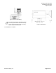
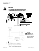
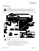
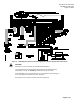
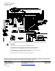
Table Of Contents

Document No. 546-14410
Installations Instructions
August 16, 2013
Siemens Industry, Inc. Page 5 of 10
Wiring Diagrams
CAUTION:
The LCM-OAVS Slow Actuation controls 24 Vac loads only. The maximum rating is 12 VA for each
DO. For higher VA requirements, 110 or 220 Vac requirements, separate transformers used to
power the load, or DC power requirements, use an interposing 220V 4-relay module (540-147).
NOTE: Refer to the unit wiring diagrams or consult with the local representative if terminations are missing or different.
Figure 7. LCM-OAVS Slow Actuation Venturi Supply/Venturi Exhaust without BTU Compensation.
CAUTION:
See Figure 5 for how to correctly wire the Offboard Air Module(s).
The LCM-OAVS has two terminal blocks with terminations numbered identically
(terminations 1 through 16). DO NOT get these mixed up with each other.
If the LCM-OAVS is not connected as shown, it is not resistant to electrical surges. It
is also susceptible to interference from other equipment.
See Figure 6 for how to wire a 4-20 mA sensor at AI 4 (optional).