BACnet Fume Hood Controller Vertical Sash with Damper or Venturi Air Valve and 2-Position Constant Volume with Damper Owner's Manual 125-5093 2015-10-14 Building Technologies
Table of contents How To Use This Manual .................................................................................................. 4 Chapter 1 – Product Overview ......................................................................................... 6 Hardware Inputs .................................................................................................................. 6 Hardware Outputs ...................................................................................................
How To Use This Manual How To Use This Manual This manual is written for the owner and user of the BACnet Fume Hood Controller. It is designed to help you become familiar with the Siemens BACnet Fume Hood Controller and its applications. This section covers manual organization, manual conventions, symbols used in the manual, and other information that will help you use this manual.
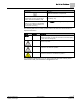
How To Use This Manual Convention Examples This symbol signifies Notes. Notes provide additional information or helpful hints. Cross references to other information are For more information on creating flowcharts, see indicated with an arrow and the page Flowcharts [→92]. number, enclosed in brackets: [→92] Placeholders indicate text that can vary based on your selection. Placeholders are specified by italicized letters, and enclosed with brackets [ ]. Type A C D H [username] [field panel #].
Chapter 1 – Product Overview Hardware Inputs Chapter 1 – Product Overview The Fume Hood Controller is a multi-application equipment controller designed to provide Direct Digital Control (DDC) for various types of Variable Air Volume (VAV) and 2-position fume hoods. The controller can operate as an independent, stand-alone, DDC room controller or it can be networked with a field panel. The controller provides all termination, input/output, system and local communication connections.
Chapter 1 – Product Overview Hardware Outputs Digital ATTN.UNATTN (through DI 2) Application 6741 Application 6742 OCC.
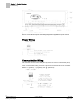
Chapter 1 – Product Overview Power Wiring Generic Controller I/O Layout. See Wiring Diagram for application specific details. Power Wiring Communication Wiring The controller connects to the field panel by means of a Floor Level Network (FLN) trunk. Communication wiring connects to the three screw terminals on the controller labeled “+” (positive), “-“ (negative), and “ ” (reference). 8 Siemens Industry, Inc.
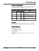
Chapter 1 – Product Overview Controller LED Indicators Controller LED Indicators The controller has eleven Light Emitting Diode (LED) indicators (see Figure BACnet Fume Hood Controller). Table Controller LEDs lists the type, the abbreviation on the controller, and the indication of each LED. Controller LEDs. LED Type Label (if present)* LED Number Indication DO DO1 - DO8 1–8 Indicates the ON/OFF status of the DO associated with it. A glowing LED indicates that the DO is energized.
Chapter 2 – Applications Basic Operation Chapter 2 – Applications Basic Operation The BACnet Fume Hood controller provides Direct Digital Control (DDC) technology for pressure independent Variable Air Volume (VAV) and Constant Volume (CV) laboratory fume hood applications. Application 6740 Fume Hood Controller 2-Position Constant Volume This application is designed for use with a constant volume or two-position fume hood in a manifold fume hood exhaust system.
Chapter 2 – Applications Application 6741 Fume Hood Controller Vertical Sash Configuration with Damper Application 6741 Fume Hood Controller Vertical Sash Configuration with Damper Application 6741 and Application 6742 are designed for use with a wide range of fume hood sash configurations connected to a manifold fume hood exhaust system.
Chapter 2 – Applications Application 6742 Fume Hood Controller Vertical Sash Configuration with Venturi Air Valve Application 6742 Fume Hood Controller Vertical Sash Configuration with Venturi Air Valve Application 6741 and Application 6742 are designed for use with a wide range of fume hood sash configurations connected to a manifold fume hood exhaust system.
Chapter 2 – Applications Application 6700 Slave Mode Application 6700 Slave Mode Application 6700 is the slave mode application for the BACnet Fume Hood Controller (see Ordering Notes for product numbers). Slave mode is the default application that comes up when power is first applied to the controller. Slave mode provides no control.
Chapter 3 – Point Database Chapter 3 – Point Database Chapter 3 presents a description of the BACnet Fume Hood Controller point database, including point descriptors, point addresses, and a listing of applications in which each point is found. Descriptor Address1 Application Description CTLR ADDRESS 01 All Identifies the controller on the FLN trunk. APPLICATION 02 All Identifies the program running in the controller.
Chapter 3 – Point Database Descriptor Address1 Application Description 767 seconds. EMER STPT 15 6740, 6741, 6742 A value of the preset FVEL STPT, in percent, that the controller uses as the setpoint when EMER ALM is ON. (Application 6740 uses EXH STPT.) LOW WARN 16 6740, 6741, 6742 Displays an ON or OFF status.
Chapter 3 – Point Database Descriptor Address1 Application Description ALRT AREA or AT ALRT AREA depending on the state of ATTN.UNATTN. EXH VOL 31 All The calculated value, in CFM (LPS), of the exhaust airflow. FLOW COEF 32 All Gain factor for the flow sensor. DUCT AREA 33 All Area of the duct, in square feet (SQM), where the air velocity sensor is located. TRANS RANGE 34 6740, 6741, 6742 The maximum range, in inches of water (PA), of the differential pressure transmitter.
Chapter 3 – Point Database Descriptor Address1 Application Description DO 7 47 6700 Spare digital output controls a 24 Vdc load with an ON or OFF status. AUTOZERO DO8 48 6740, 6741, 6742 Drives the Offboard Air Module(s) in order to calibrate the flow sensor(s). Do not use or manually set this point. DO 8 48 6700 Spare digital output controls a 24 Vdc load with an ON or OFF status. AI 3 49 6741, 6742 Optional input for External Face Area or Airflow sensor.
Chapter 3 – Point Database Descriptor Address1 Application Description at the controller board. VERT WIDTH2 66 6741, 6742 Defines the overall width of the vertical sash wired to sash 2 at the controller board. VSASH HGHT1 67 6741, 6742 Defines the overall height of the vertical sash wired to sash 1 at the controller board. VSASH HGHT2 68 6741, 6742 Defines the overall height of the vertical sash wired to sash 2 at the controller board.
Chapter 3 – Point Database Descriptor Address1 Application Description AO2 RANGE 90 6741, 6742 Scaling for the Analog Output (AO2) point. To get the correct output, the slope and intercept of this point must match the point database of the room controller. AO2 DEADBAND 91 6740, 6741, 6742 When EXH FLOW and FLOW STPT are different by more than the AO2 DEADBAND, the AO2 FLOW SIG changes from setpoint to actual flow.
Chapter 3 – Point Database Descriptor Address1 Application Description valve. ODP DISPLAY 125 6740 AVE FACE VEL 126 6741, 6742 AVE EXH VOL 126 6740 PPCL STATE 127 6740, 6741, 6742 1) Controls the function of the ODP display. It will display either CFM divided by 10 or HI FLOW / LO FLOW. The filtered face velocity that displays on the ODP. The filtered exhaust volume that displays on the ODP.
Chapter 4 – Basic Service and Maintenance Basic Service Information Chapter 4 – Basic Service and Maintenance This chapter describes corrective measures you can take should you encounter a problem when using a BACnet Fume Hood Controller. You are not required to do any controller troubleshooting. You may want to contact your local Siemens Industry representative if a problem occurs or you have any questions about the controller.
Chapter 4 – Basic Service and Maintenance Safety Features Safety Features The controller board stores the controller's address, applications, and point values. In the event of a power failure or a reset, these values are retrieved from the controller's permanent memory and are used by the controller unless overridden by a field panel. If one of the following conditions occurs, the controller will activate safety features present in its fail-safe mode. Sensor failure. Loss of power.
Glossary Glossary This glossary contains the collected terms and acronyms that are used in Siemens BACnet PTEC and TEC Controllers. For definitions of point database descriptors, see Chapter 3 - Point Database, in this manual. airflow Rate at which a volume of air moves through a duct. Usually expressed in cubic feet per minute (cfm) or liters per second (lps). algorithm Mathematical formula and control logic that uses varying inputs to calculate an output value. AVS Air Velocity Sensor.
Glossary Demand Control Ventilation A control algorithm that provides for the control or reduction of outdoor air intake below design rates when the actual occupancy of spaces served by the system is at less than design occupancy. DCV Demand Control Ventilation. DDC Direct Digital Control. Direct digital control The automated control of a condition or process by a digital device (computer). DO Digital Output. Physical output point that sends a two-state signal (ON/OFF, OPEN/CLOSED, YES/NO).
Glossary HMI Human Machine Interface. Terminal and its interface program that allows you to communicate with a field panel or equipment controller. Occupancy sensor A control device that detects presence of people in a space by using infrared or ultrasonic technology. Occupancy sensors are used to save energy by controlling lighting and temperature and, along with CO2 sensors, to provide control input of demand control ventilation (DCV) algorithms.
Glossary UI Universal Input. Can be used as an AI or DI. An AI input is a point receiving a signal that represents a condition that has more than two states. A DI input is a physical input point that receives a two-state signal. unbundle Term used to describe the entering of a point that resides in a controller's database into the field panel's database so that it can be monitored and controlled from the field panel. VAV Variable air volume.
Index Index A actuators, 9 damper actuator, 9 valve actuator, 9 algorithm, 23 application, slave mode overview, 13 B basic operation, 10 basic service information, 21 C centralized control, 23 Chilled Beam, 23 CO2, 23 control loop, 23 CV, 23 D DCV, 24 DDC, 24 Demand Control Ventilation, 24 Direct digital control, 24 Direct Digital Control (DDC), 10 DO, 24 E English units, 24 equipment controller, 24, 25 F field panel, 6 FLN, 24 Floating Control, 24 Floor Level Network (FLN), 8 loopout, 24 M m
Issued by Siemens Industry, Inc. Building Technologies Division 1000 Deerfield Pkwy Buffalo Grove IL 60089 Tel. +1 847-215-1000 Document ID 125-5093 Edition 2015-10-14 © Siemens Industry, Inc., 2015 Technical specifications and availability subject to change without notice.