
Operating Instructions
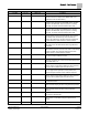
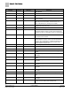
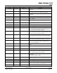
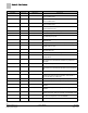
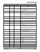
Table Of Contents

Chapter 3 – Point Database
18
Siemens Industry, Inc. Owner's Manual 125-5093
Building Technologies 2015-10-14
Descriptor
Address
1
Application
Description
at the controller board.
VERT WIDTH2 66 6741, 6742 Defines the overall width of the vertical sash wired to sash 2
at the controller board.
VSASH HGHT1 67 6741, 6742
Defines the overall height of the vertical sash wired to sash 1
at the controller board.
VSASH HGHT2 68 6741, 6742
Defines the overall height of the vertical sash wired to sash 2
at the controller board.
TRACK HEIGHT 69 6741, 6742 Measurement, in inches (cm), of the vertical track in a multi-
vertical sash fume hood.
BYPASS HGHT 70 6741, 6742 The height of the bypass opening of the fume hood.
BYPASS OPEN 71 6741, 6742 The effective bypass area in percent.
FAIL AREA 72 6741, 6742 When a sash sensor fails, the controller controls to the face
area defined by this point.
EXTERNAL A 73 6741, 6742
When AI 3 is used to input an external face area, the value is
displayed here.
MAX EXT AREA 74 6741, 6742 Scaling for the external face area Analog Input (AI 3) point.
MIN EXTVOLTS 75 6741, 6742 Minimum voltage value for external face area input range
(typically 0.0V or 1.0V).
CAL EXH VLV 78 6742 YES or NO point used to calibrate EXH AO3 to the
associated flow rate.
STARTUP DI4 78 6740 Determines if DI4 is used to change the STARTUP MODE.
EXH VLV STAT 79 6742 PASS or FAIL point used to indicate if the last calibration
attempt passed.
EXH MAX 80 6741, 6742, 6700 Maximum flow setpoint allowed. EXH MAX will override the
FVEL STPT if the calculated FLOW STPT is greater than
EXH MAX.
EXH HI STPT 80 6740 The high flow setpoint used in EXH STPT.
EXH MIN 81 6741, 6742, 6700 Minimum flow setpoint allowed. EXH MIN will override the
FVEL STPT if the calculated FLOW STPT is less than EXH
MIN.
EXH LO STPT 81 6740 The low flow setpoint used in EXH STPT.
FVEL STPT 83 6741, 6742 The face velocity setpoint in feet per minute (m/s) that is
maintained by the Fume Hood Controller. Valid values: 0
through 225 ft/min (0-1.2954 m/s).
OCC FV SET 84 6741, 6742 The face velocity setpoint during occupied operation.
UNOC FV SET 85 6741, 6742 The face velocity setpoint during unoccupied operation.
OCC LOW FV 86 6741, 6742
(Optional)
The low face velocity setpoint during occupied
operation.
OCC HIGH FV 87 6741, 6742
(Optional)
The high face velocity setpoint during occupied
operation.
OCC DELAY 88 6741, 6742 This point delays the OCC.UNOCC function, a user defined
number of seconds, when the controller is in UNATTN mode.
EXH SIG AO2 89 6740, 6741, 6742 Indicates the exhaust flow setpoint. The output is 1 to 10
Vdc, which corresponds to 0 to AO2 RANGE.
AO2 89 6700 Spare analog output is a 9 to 10 Vdc output.