LCM-OAVS Room Pressurization with Two Fast-acting Venturi Air Valves (One Exhaust, One Supply) and Hot Water Reheat, Application 2920 Application Note 140-1307 2015-07-07 Building Technologies
Table of Contents Overview ............................................................................................................................. 5 Hardware Inputs .................................................................................................................. 6 Hardware Outputs ................................................................................................................ 7 Ordering Notes .............................................................................
Return from Power Failure and Venturi Air Valve Action ................................................... 34 Operation of AVS FAILMODE ........................................................................................... 34 Fail Mode Operation .......................................................................................................... 35 Application Notes ............................................................................................................... 37 Wiring Diagrams ..
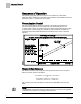
Overview Hardware Inputs Overview Application 2920 controls pressurization, ventilation, and room temperature in a laboratory room served by one single-duct supply terminal with a reheat coil, one general exhaust terminal, and up to six fume hoods (multiple fume hood flow signals must be averaged using an averaging and scaling module. Pressurization is controlled by maintaining a selected difference between supply and exhaust airflows.
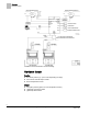
Overview Hardware Inputs Ventilation and Pressurization Control Drawing. Hardware Inputs Analog Air velocity sensor (s) – (one or two depending on setup) Fume hood controller input or FFM Room temperature sensor Digital Occupancy button (option on room temperature sensor) (Optional) Occupancy switch (Optional) Alarm switch 6 Siemens Industry, Inc.
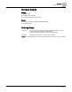
Overview Hardware Outputs Hardware Outputs Analog Reheat valve Supply Venturi Air Valve General exhaust Venturi Air Valve Digital Autozero Solenoid in Offboard Air Module (DO 8) (Optional) Alarm Ordering Notes 550-767CN LCM-OAVS Room Pressurization with Two Fast-acting Venturi Air Valves (One Suppy, One Exhaust) and Hot Water Reheat Requires Offboard Air Module(s) – order and ship separately 550-819B Offboard Air Module (OAM) – order and ship separately NOTE: 550-767CNis designed to work
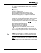
Sequence of Operation Pressurization Control Sequence of Operation The following paragraphs present the sequence of operation for LCM-OAVS Application 2620: Variable Air Volume Room Pressurization with HW Reheat and Two Venturi Air Valves — One Exhaust, One Supply. Pressurization Control The goal of pressurization control is to maintain a fixed difference between the volumes of total supply air and total exhaust air (see the following figure).
Sequence of Operation Occupancy Application 2920 has the ability to maintain a different volume differential setpoint during occupied mode than during unoccupied mode. When OCC.UNOCC = OCC, VOL DIF STPT = OCC DIF STPT. When OCC.UNOCC = UNOCC, VOL DIF STPT = UOC DIF STPT. Occupancy The controller keeps track of the occupancy status of the room and uses that information for the following purposes: To select minimum and maximum flow rates for each air terminal.
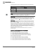
Sequence of Operation Active Flow Minimums and Maximums The following table shows what is enabled when OCC ENA is at a particular value. OCC ENA Values. OCC ENA (value) 0 (default) Description Both OCC BUTN DI1 and OCC SWIT DI2 are disabled. 1 Only OCC BUTN DI1 is enabled. 2 Only OCC SWIT DI2 is enabled. NOTE: OCC ENA does not allow both OCC BUTN DI1 and OCC SWIT DI2 to be enabled at the same time. If OCC ENA is set greater than 2, it will default to 0.
Sequence of Operation VAV versus CV Control VAV versus CV Control In Application 2920, VAV means that temperature is controlled by varying flow in conjunction with the reheat valve. CV means that temperature is controlled by using the reheat valve only. The supply and general exhaust can still change in CV mode to keep the volume differential setpoint constant. This may be necessary if HOOD VOL is varying.
Sequence of Operation Flow Tracking – Supply Tracks Exhaust vs. Exhaust Tracks Supply Flow Tracking – Supply Tracks Exhaust vs. Exhaust Tracks Supply The Supply Tracks Exhaust (STE) and Exhaust Tracks Supply (ETS) feature is configured by setting TRACK MODE to STE or ETS to help the controller meet the pressurization needs of the controlled space, such as for negative or positive pressure. TRACK METHOD is used to determine what is being tracked – a flow value or a setpoint value.
Sequence of Operation Calculating Exhaust Flow Setpoint TRACK METHOD TRACK METHOD is a point associated with TRACK MODE. TRACK MODE determines which airflow (supply or general exhaust) gets tracked and which airflow does the tracking. TRACK METHOD determines how tracking is accomplished. If TRACK MODE is set to ETS and TRACK METHOD is set for FLOW tracking, the general exhaust flow setpoint is calculated according to the measured value, SUP AIR VOL.
Sequence of Operation Calculating Supply Flow Setpoint When Exhaust Tracks Supply (ETS) flow tracking is used, the general exhaust airflow setpoint is calculated the same during both VAV and CV operation, as follows: To calculate GEX FLO STPT, the controller determines the general exhaust airflow value that pressurizes the room based on the values of VOL DIF STPT, OTHER EXH, OTHER SUP and either SUP FLO STPT or SUP AIR VOL depending on the value of TRACK METHOD.
Sequence of Operation Ventilation – VAV Mode Ventilation – VAV Mode During VAV operation, the ventilation works as follows: OCC SUP MIN, the occupied supply minimum, is used to ensure that the room receives enough supply air for proper ventilation during the occupied mode. UOC SUP MIN is used to ensure that the room receives enough supply air for proper ventilation during the unoccupied mode.
Sequence of Operation AVS Calibration AVS Calibration Calibration of the air velocity transducer(s) is periodically required to maintain accurate air velocity readings. Depending on the value of CAL SETUP, calibration takes place either at fixed time intervals or whenever the application goes into unoccupied mode. When calibration is in progress, CAL AIR equals YES. After calibration, CAL AIR returns to NO. The application uses Autozero Modules connected to AUTOZERO DO8.
Sequence of Operation Table Access Feature (Mode 1, 3) Table values are the result of the application’s analysis of the voltages that drove the actuator during calibration and the resulting airflow values in cfm. To hedge against airflow accuracy slippage, the supply (or general exhaust) air velocity feedback loop is used along with the table statement to maintain correct airflow out of the Venturi.
Sequence of Operation Table Access Feature (Mode 1, 3) a) These voltage/flow values constitute the “low flow” element (or “point”) for the Supply and the General Exhaust Venturi Air Valves. They are shown here with factory default values. They are not altered during calibration—they must be set manually. However, they only need to be set if the Venturi Air Valve is going go be operating at low flow settings of less than 350 fpm. Otherwise, they can be left at default and ignored.
Sequence of Operation Venturi Table Evaluation and Editing (Mode 1, 3) This application has a table statement edit feature that allows you to view and edit the voltage/flow values in the table. This is useful for fine tuning the air valve to meet precise room flow setpoints and for diagnosing/editing problematic voltage/flow curves (see the Table Venturi Air Valve Table Statement). Problematic Venturi Air Valve Voltage/Flow Curves.
Sequence of Operation Venturi Table Evaluation and Editing (Mode 1, 3) 2. Edit the inactive table values. Since you have just switched the active and inactive portions of the table in Step 1, the inactive values are now identical to what the active values were moments ago. You can now edit these new inactive values by using V TABLE PT to reference them in TABLE FLOW and TABLE VOLTS. The Table Venturi Air Valve Table Statement explains this in more detail. 3. Set V TABLE PT once again to the swap value.
Sequence of Operation Venturi Table Evaluation and Editing (Mode 1, 3) Venturi Air Valve Table Statement V TABLE PT 1 Setting V TABLE PT to 1 takes the flow (cfm) and voltage values from the first element of the active supply table and displays them in TABLE FLOW and TABLE VOLTS where they can be edited. (This is the only active supply element (or “point”) that can be directly edited.) Flow and voltage values are not allowed to exceed those in active supply point 2.
Sequence of Operation Venturi Table Evaluation and Editing (Mode 1, 3) Venturi Air Valve Table Statement V TABLE PT Description 32 - 46 This portion of the table (32 through 46) can be viewed but not edited directly. When a point is selected (that is, when V TABLE PT is set to a value 32 through 46), the corresponding flow and voltage values are displayed in TABLE FLOW and TABLE VOLTS.
Sequence of Operation PID Only (Mode 2) PID Only (Mode 2) NOTE: The default P gain value is intended for PID operation in conjunction with the Venturi table. The P gain and Venturi table work together to provide an appropriate response to setpoint changes. When operating without the Venturi table in PID Only mode, the application is slower to respond. Therefore, you should adjust the P gain as needed when operating in PID Only mode to ensure acceptable performance.
Sequence of Operation Open Loop (Mode 3) It may not be necessary to enter 0 values since 0 values are initially in the table by default when direct acting is selected. Point Flow Volt 1 0 10.0 2 0 10.0 15 0 10.0 16 1200 0.0 Example 2 - Table with CFM End Limits – reverse acting It may not be necessary to enter 10.0 values since 10.0 values are initially in the table by default when reverse acting is selected.
Sequence of Operation Operating Without a Supply or Exhaust 8 340 3.2 9 390 3.5 10 521 3.8 11 531 4.1 12 598 4.9 13 691 5.8 14 798 7.0 15 0 0 16 1200 10 Example 5 - Multi-point Table The point values above are for the exhaust table. Open loop supply operation is similar, but the points used are 1 through 16; not 30 through 46. Since the actual airflow being measured is 0, the heating safety requirement for minimum airflow is not met and heating will not occur.
Sequence of Operation Airflow Control Mode 2 - Operates with a PID loop, but no Venturi table. In this mode, the controller operates with PID control based on a flow sensor input, but the Venturi table is not used. See the PID Only Mode section later in this document for specific information on this mode. Mode 3 - Operates with Venturi table, but no PID loop In this mode, the controller operates open loop (without a flow sensor). There is no PID control.
Sequence of Operation Room Temperature and Setpoint NOTE: If HI and LO LIMIT are set equal, then the feedback loop will always be active as long as the supply air velocity is greater than 350 cfm. The interaction between the table statement and the supply air velocity feedback loop is summarized as follows: When the supply air volume is near setpoint, the table statement controls it.
Sequence of Operation Room Temperature and Setpoint Room Temperature and Setpoint The application uses the CTL STPT as the setpoint for the Room Temperature PID Loop. When CTL STPT is not overridden and not being controlled by a field panel, then ROOM STPT and CTL STPT are related to each other as follows: If ROOM STPT is greater than RM STPT MAX, then CTL STPT is set equal to RM STPT MAX. If ROOM STPT is less than RM STPT MIN, then CTL STPT is set equal to RM STPT MIN.
Sequence of Operation Room Unit Operation Room Unit Operation Sensor Select SENSOR SEL is a configurable, enumerated point (values are additive). This point tells the controller what type of room unit is being used and how to handle loss of communication, for more information see Fail Mode Operation [➙ 35]. It also provides the ability to enable the optional RH and CO2 sensors and indicates which thermistor type is connected.
Sequence of Operation Temperature Control Loop Room CO2 RM CO2 displays the CO2 value in units of parts-per-million (PPM). RM CO2 (from the digital 2200/2300 room units) can be used with PPCL in the PTEC/ATEC controller or unbundled for control or monitoring purposes. Room RH RM RH displays the relative humidity value in percent. RM RH can be used for PPCL in the PTEC or unbundled for control or monitoring purposes. RM RH displays the relative humidity value in percent.
Sequence of Operation Alarms does not calculate the supply flow setpoint. Instead, it calculates the amount of supply airflow needed for cooling (TEMP CTL VOL). If this value is compatible with correct room pressurization, it is used as the supply flow setpoint. If not, the actual setpoint, SUP FLO STPT, may be higher or lower than TEMP CTL VOL. As the value of TEMP LOOPOUT moves from START to 100%, TEMP CTL VOL is modulated from the supply minimum to the supply maximum.
Sequence of Operation Alarms GEX AIR VOL stays below the currently active general exhaust box minimum, for a time at least equal to VENT ALM DEL. It is turned off only when all of the following conditions are true: The TOTL SUPPLY stays above the alarm level, for a time at least equal to the alarm delay. SUP AIR VOL stays above the currently active supply minimum, for a time at least equal to VENT ALM DEL.
Sequence of Operation Alarms Local Annunciation ALARM ENA is an analog point whose value determines whether or not a particular alarm activates ALARM DO7. For ALARM ENA, the terms enabled and not enabled do not mean that a particular alarm is enabled or not. It means whether or not a particular alarm will or will not activate ALARM DO7. For example, if ALARM ENA is set to 1 (Vent Alarm Enabled) and a ventilation alarm occurs, then both VENT ALM and ALARM DO7 will turn on.
Sequence of Operation Return from Power Failure and Venturi Air Valve Action Network Annunciation If the LCM is connected to a field panel, alarms can be reported using the workstation software, or by using a printer that is set up in a building manager’s office to receive alarms. Points in the controller must be entered in the field panel’s point database (referred to as unbundling) and defined as alarmable.
Sequence of Operation Fail Mode Operation Sensors (AVS) fail. It can handle both positively pressurized rooms and negatively pressurized rooms. The default value of AVS FAILMODE is 0. This default causes both the supply and general exhaust to hold their current position when an AVS fails. Open Supply, Open Exhaust and Close Supply, Close Exhaust are not defined AVS FAILMODE states. AVS Failure and AVS FAILMODE Table Values.
Sequence of Operation Fail Mode Operation * If MAX HOOD VOL is set to 0, a “Failed” status of HOOD VOL will not initiate a failure in TOTL EXHAUST or VOL DIFFRNC. See Fume Hood Flow Input.
Sequence of Operation Application Notes Electronic Actuator – If the actuator fails, typically, flow control is lost and alarms are triggered. Upon loss of power or control signal to the actuator, it will move to its fail-safe position. Room Temperature Sensor – If the room temperature sensor fails while CTL TEMP is not overridden or is not being adjusted by a field panel, then ROOM TEMP and CTL TEMP both display as “Failed” and temperature control is suspended at the current value of TEMP LOOPOUT.
Sequence of Operation Application Notes TRACK MODE to 3. (a value of 3 = ETS Flow Tracking, should be used for both the occupied and unoccupied modes). SUP FLO COEF to 0. When SUP FLO COEF equals 0, SUP AIR VOL will always read 0, but will never show as Failed. OCC SUP MIN and UOC SUP MIN to 0. If these two points are not set to 0, SUP AIR VOL— will read 0 since SUP FLO COEF was set to 0—will be less than the supply box minimum, resulting in a false ventilation alarm.
Sequence of Operation Wiring Diagrams Wiring Diagrams Offboard Air Module Wiring. CAUTION The LCM-OAVS has two terminal blocks with terminations numbered identically (terminations 1 through 16). DO NOT mix these up with each other. If the LCM-OAVS is not connected as shown, it is not resistant to electrical surges. It is also susceptible to interference from other equipment. CAUTION A separate power supply is required if a 4-20 mA sensor is used.
Sequence of Operation Wiring Diagrams NOTE: If the voltage/current switch is set to current and a 4 to 20 mA sensor is connected to an AI, then special wiring requirements must be followed. NOTE: The controller’s DOs control 24 Vac loads only. The maximum rating is 12 VA for each DO.
Sequence of Operation Wiring Diagrams BACnet LCM-OAVS with Hot Water Reheat and Two Venturi Air Valves (One Exhaust, One Supply) -- Application 2920 Wiring Diagram. 41 Siemens Industry, Inc.
Point Databse Application 2920 Point Databse Application 2920 Point Number Descriptor Factory Default (SI Units) Eng Units (SI Units) Slope (SI Units) Intercept (SI Units) On Text Off Text 1 CTLR ADDRESS 99 -- 1 0 -- -- 2 APPLICATION 2997 -- 1 0 -- -- 3 TEMP OFFSET 0.0 (0.0) DEG F (DEG C) 0.25 (0.14) -31.75 (-17.78) -- -- {04} ROOM TEMP 74.0 (23.44888) DEG F (DEG C) 0.25 (0.14) 48.0(8.88888) -- -- 5 OCC DIF STPT 400 (188.7599) CFM (LPS) 4 (1.8876) -8000 (-3775.
Point Databse Application 2920 Point Number Descriptor Factory Default (SI Units) Eng Units (SI Units) Slope (SI Units) Intercept (SI Units) On Text Off Text {30} GEX AIR VOL 0 (0.0) CFM (LPS) 4 (1.8876) 0 -- -- {31} OCC SUP MAX 3400 (1604.46) CFM (LPS) 4 (1.8876) 0 -- -- {32} OCC SUP MIN 340 (160.446) CFM (LPS) 4 (1.8876) 0 -- -- {33} OCC GEX MAX 1100 (519.09) CFM (LPS) 4 (1.8876) 0 -- -- {34} OCC GEX MIN 600 (283.14) CFM (LPS) 4 (1.
Point Databse Application 2920 Point Number Descriptor Factory Default (SI Units) Eng Units (SI Units) Slope (SI Units) Intercept (SI Units) On Text Off Text {62} CAL SUP VLV NO -- -- -- YES NO 65 ROOM P GAIN 20.0 (36.0) -- 0.25 (0.45) 0 -- -- 66 ROOM I GAIN 0.01 (0.018) -- 0.001 (0.0018) 0 -- -- {67} UOC GEX MAX 1000 (471.9) CFM (LPS) 4 (1.8876) 0 -- -- {68} UOC GEX MIN 500 (235.95) CFM (LPS) 4 (1.8876) 0 -- -- {69} TOTL SUPPLY 0 (0.0) CFM (LPS) 4 (1.
Point Databse Application 2920 Point Number Descriptor Factory Default (SI Units) Eng Units (SI Units) Slope (SI Units) Intercept (SI Units) On Text Off Text {94} CAL AIR NO -- -- -- YES NO 95 CAL SETUP 4 -- 1 0 -- -- 96 CAL TIMER 12 HRS 1 0 -- -- 97 SUPDUCT AREA 1.0 (0.09292) SQ. FT (SQ M) 0.025 (0.
Point Database (Slave Mode) Application 2997 Point Database (Slave Mode) Application 2997 Point Number Descriptor Factory Default (SI Units) Eng Units (SI Units) Slope (SI Units) Intercept (SI Units) On Text Off Text 1 CTLR ADDRESS 99 -- 1 0 -- -- 2 APPLICATION 2997 -- 1 0 -- -- 3 TEMP OFFSET 0.0 (0.0) DEG F (DEG C) 0.25 (0.14) -31.75(-17.78) -- -- {04} ROOM TEMP 74.0 (23.44888) DEG F (DEG C) 0.25 (0.14) 48.0 (8.88888) -- -- {13} ROOM STPT 74.0 (23.
Point Database (Slave Mode) Application 2997 Point Number Descriptor Factory Default (SI Units) Eng Units (SI Units) Slope (SI Units) Intercept (SI Units) On Text Off Text {84} AI 5 74.0 (23.496) DEG F (DEG C) 0.5 (0.28) 37.5(3.056) -- -- {94} CAL AIR NO -- -- -- YES NO 95 CAL SETUP 4 -- 1 0 -- -- 96 CAL TIMER 12 HRS 1 0 -- -- 97 DUCT AREA 1 1.0 (0.09292) SQ. FT (SQ 0.025 M) (0.
Issued by Siemens Industry, Inc. Building Technologies Division 1000 Deerfield Pkwy Buffalo Grove IL 60089 Tel. +1 847-215-1000 Document ID 140-1307 Edition 2015-07-07 © Siemens Industry, Inc., 2015 Technical specifications and availability subject to change without notice.