
Application
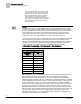

Sequence of Operation
Venturi Table Evaluation and Editing (Mode 1, 3)
20
Siemens Industry, Inc.
Application Note, App 2920
140-1307
2015-07-07
2. Edit the inactive table values.
Since you have just switched the active and inactive portions of the table in
Step 1, the inactive values are now identical to what the active values were
moments ago. You can now edit these new inactive values by using V TABLE
PT to reference them in TABLE FLOW and TABLE VOLTS. The Table
Venturi
Air Valve Table Statement
explains this in more detail.
3. Set V TABLE PT once again to the swap value. This places the newly edited
inactive values back into the active portion of the table statement (again, the active
and inactive portions of the table are simply swapped). However, before the swap
is finalized, the application analyzes your proposed values using the same logic as
in a regular calibration sequence.
⇨
If your proposed values are good, then the swap is made and the edited
values are accepted into the active supply (or exhaust) portion of the
table. Depending on which portion of the table you were editing, SUP
VLV STAT or GEX VLV STAT is marked PASS and control of the
Venturi Air Valve resumes.
⇨
However, if it is marked FAIL, you must gather and view the voltage/flow
values to see where the problem lies.
NOTES:
1. If
SUP FLO COEF is 0, the table edit feature uses a supply flow coefficient of 1.
2. If SUPDUCT AREA is 0, the table edit feature uses a supply duct area of 1 square
foot.
3. If
GEX FLO COEF is 0, the table edit feature uses a general exhaust flow
coefficient of 1.
4. If
GEXDUCT AREA is 0, the table edit feature uses a general exhaust duct area of
1 square foot.
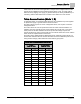
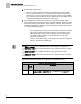
The following table lists all values for V TABLE PT and describes their use.
Venturi Air Valve Table Statement
V
TABLE
PT
Description
0
Default value for V TABLE PT. When V TABLE PT equals 0, changes to
TABLE FLOW or TABLE VOLTS are ignored. Setting V TABLE PT to 0
cancels an edit session.