
Application

Sequence of Operation
Temperature Control Loop
30
Siemens Industry, Inc.
Application Note, App 2920
140-1307
2015-07-07
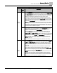
Room CO2
RM CO2 displays the CO
2
value in units of parts-per-million (PPM). RM CO2 (from the
digital 2200/2300 room units) can be used with PPCL in the PTEC/ATEC controller or
unbundled for control or monitoring purposes.
Room RH
RM RH displays the relative humidity value in percent. RM RH can be used for PPCL
in the PTEC or unbundled for control or monitoring purposes.
RM RH displays the relative humidity value in percent.
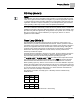
Temperature Control Loop
Whenever the controller is in VAV control mode, the temperature control portion of
Application 2920 works as follows:
The controller adjusts the supply airflow and the reheat valve as necessary to maintain
CTL TEMP at CTL STPT. (When neither CTL TEMP nor CTL STPT is overridden, this
means the controller tries to maintain ROOM TEMP at ROOM STPT.) The temperature
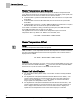
control loop calculates the value of TEMP LOOPOUT. This value is used to sequence
the cooling flow and the heating valve. See the following figure. The loop is tuned by
adjusting the values of the feedback gains (ROOM P GAIN and ROOM I GAIN and the
sample interval, LOOP TIME.
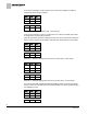
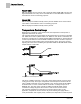
Temperature Control Sequence.
The range of TEMP LOOPOUT is 0 to 100%. Higher values indicate a need for more
cooling (or less heat). The Figure
Temperature Control Sequence
shows that as the
value of TEMP LOOPOUT moves from START to 0%, and the reheat VALVE CMD is
modulated from 0 to 100%. VALVE CMD is converted to a voltage and put out on
REHEAT A01. The setup points, VALVE CLOSED and VALVE OPEN, tell the
controller the voltage range the valve needs to reach at each end of its stroke.
The controller modulates the cooling flow in sequence with the valve. In this
application, temperature control is not the only factor affecting the supply airflow—
room pressurization has a higher priority. Therefore, the temperature control sequence