
Basic Documentation
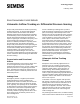
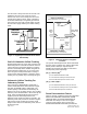
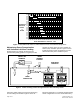
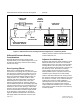
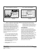
Table Of Contents

from the room is always less than the amount of air
supplied to the room. This creates an excess
amount of air in the room causing room air to flow
outward to the adjacent areas. Figure 1 illustrates
the airflow relationship of a negatively pressurized
room where the total room exhaust airflow exceeds
the total room supply airflow by the airflow tracking
offset.
AIRFLOW
TRACKING
OFFSET
TOTAL ROOM
SUPPLY
AIRFLOW
TOTAL ROOM
EXHAUST
AIRFLOW
Figure 1. Negatively Pressurized Room Airflow
Relationship.
Goal of Volumetric Airflow Tracking
Airflow tracking does not ensure that a specific room
differential pressure value will be attained. However,
it does ensure that the desired negative or positive
pressure relationship will be attained along with the
desired directional airflow (into or out of the room).
Since the goal of room pressurization is mainly to
ensure proper directional airflow, volumetric airflow
tracking is a very reliable way of achieving this goal.
Volumetric Airflow Tracking For
Laboratory Rooms
Page 2 of 8 Siemens Industry, Inc.
Document No. 149-977
Figure 3 shows a LABORATORY ROOM with a
TOTAL ROOM EXHAUST AIRFLOW that is higher
level than the ROOM SUPPLY AIRFLOW. (The
relative quantity of the airflows is indicated by the
difference in size of the airflow arrows.) The resulting
deficiency in the ROOM SUPPLY AIR created by the
larger TOTAL ROOM EXHAUST AIR creates the
negative pressure relationship between the
laboratory room and the two adjacent corridors. The
laboratory room static pressure is therefore negative
with respect to both corridors and transfer air will
always tend to flow into the laboratory room, which is
the desired result.
PERSONNEL CORRIDOR
O
(POSITIVE WITH RESPECT TO LABORATORY)
LABORATORY ROOM
(NEGATIVE)
ROOM
SUPPLY
AIR
TOTAL ROOM
EXHAUST AIR
TRANSFER
AIRFLOW
INTO
ROOM
SERVICE CORRIDOR
0
(POSITIVE WITH RESPECT TO LABORATORY)
TRANSFER
AIRFLOW
INTO
ROOM
Figure 2. Laboratory Room at a Negative
Pressure.
The specific relationship between Room Differential
Pressure, Room Leakage Area, and the Differential
Airflow (transfer airflow) is expressed by the
following two equations that apply to Inch-Pound
and SI (metric) units respectively:
(IP) Q = 2610 A (dP)
1/2
Q is the differential airflow in CFM
A is the total room leakage area Square Feet
dP is the differential pressure Inches of H
2
0
(SI) Q = 840 A (dP)
1/2
Q is the differential airflow in Liters per Second
A is the total room leakage area in Square Meters
dP is the differential pressure in Pascals
Room Pressurization Factors
Figure 3 contains a graph the shows the relationship
between DIFFERENTIAL PRESSURE, ROOM
LEAKAGE AREA, and ROOM DIFFERENTIAL
AIRFLOW. The family of curves on the graph
represent room leakage area (in square feet).
ROOM DIFFERENTIAL AIRFLOW (the difference