Two-State Constant Volume Fume Hood Controller Owner’s Manual 125-5033 Rev.
Rev. AA, September 2007 NOTICE The information contained within this document is subject to change without notice and should not be construed as a commitment by Siemens Building Technologies, Inc. Siemens Building Technologies, Inc. assumes no responsibility for any errors that may appear in this document. All software described in this document is furnished under a license and may be used or copied only in accordance with the terms of such license.
Table of Contents How To Use This Manual ............................................................................................. VII Manual Organization ................................................................................................. VII Manual Conventions.................................................................................................. VII Manual Symbols ........................................................................................................
Applications .................................................................................................................. 11 Fume Hood Controller: 2-Position Constant Volume ............................................... 11 Basic Operation ............................................................................................................ 12 High and Low Exhaust Flow Control ......................................................................... 12 Control Loops ............................
How To Use This Manual This section covers manual organization, conventions, and symbols used in the manual, and other information that will help you understand and use a Laboratory Room Controller — Electronic Output. Manual Organization This manual contains the following sections: • Chapter 1 Product Overview describes the hardware components and the accessories that are used with the controller. • Chapter 2 Applications describes the control applications available in the controller.
Manual Symbols The following table lists symbols that are used to draw your attention to important information. Notation Symbol Meaning CAUTION: Indicates that equipment damage or loss of data may occur if the user does not follow a procedure as specified. WARNING: Indicates that personal injury or loss of life may occur to the user if a procedure is not performed as specified. Datamate Software Datamate is a customer software tool for all controller communications.
1 Product Overview Introduction The Fume Hood Controller is an equipment controller designed to provide Direct Digital Control (DDC) for 2 position fume hoods. The controller consists of a controller board and a controller enclosure. The controller board (Figure 1) is the central computing/controlling component of the system.
Fume Hood Controller Owner's Manual Table 1. Fume Hood Controller – Electronic Output Applications. Application 940 Description 2 Position Fume Hood Controller Ordering Notes Fume Hood Controller – Electronic Output (940) 546-00750 Figure 1. Fume Hood Controller Board . 2 Siemens Building Technologies, Inc.
Product Overview Hardware Inputs Analog • Differential pressure transmitter • Operator Display Panel (ODP) • ATTN.UNATTN (through DI1) • OCC.UNOCC (through DI1) Digital Hardware Outputs Analog • AO-E/AO-P module (Floating Control) • Operator Display Panel (ODP) • AO2 (Flow Signal, 1 to 10 Vdc) • FLN communications trunk • DO3 (24 Vac, Alarm/Hi.Low Output) Digital Power Wiring The controller is powered by 24 Vac.
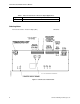
Fume Hood Controller Owner's Manual FLN TRUNK + - S TEC0470R1 LAB00140R1 (SHIELD) 24V COMMON 24V HOT GROUND Figure 2. Power Wiring. (SHIELD) (-) (+) (-) (+) Figure 3. Communication Wiring. Controller LED Indicators The controller has six Light Emitting Diode (LED) indicators. See Table 2. Table 2. Controller LEDs. LED Type Label (if present)* Indication DO LED 1 - LED 3 Transmit TX Indicates, when flashing, that the controller is transmitting information to the field panel.
Product Overview Pressing the Emergency Purge button a second time reverts the Fume Hood Controller to normal operation for the current conditions. HI/LO: HI/OFF Select button – Pressing this button changes the controller from a high flow setpoint to a low flow setpoint and back again or changes the controller from a high flow setpoint to and OFF state and back again. Auxiliary Button – The Auxiliary buttons are not used currently.
Fume Hood Controller Owner's Manual The terminal is available in diameters ranging from 4 to 18 inches. The terminal is available in a variety of end configurations to match the ductwork construction. It is also available in TEFLON® coated 18-gauge steel for highly corrosive environments. Figure 5. Laboratory Exhaust Air Terminal. Venturi Air Valves The Venturi Air Valve is a pre-packaged, easy to install airflow measurement and control station. See Figure 6.
Product Overview High Speed Electronic Actuation The High speed electronic actuator assembly consists of two parts, the electronic actuator and the interface board. The actuator is connected to the exhaust flow control device in the fume hood exhaust duct. The electronic actuator assembly is used because of its small size and quick response time.
Fume Hood Controller Owner's Manual Low Speed Electronic Actuation Alternately, when speed of response is not an issue, slower speed electronic actuation may be used. This can be used when the change-of-state between High and Low can take place in 15 seconds or more. Low Speed Actuator (GMA13x). Pneumatic Actuation The pneumatic actuator is connected to an exhaust flow control device in the fume hood exhaust duct. The standard pneumatic actuator (Figure 8) used with the Fume Hood Controller is the No.
Product Overview Figure 8. Pneumatic Actuator. Analog Output-Pneumatic (AO-P) Module The Analog Output-Pneumatic (AO-P) Module is an electric-to-pneumatic interface between the Fume Hood Controller and the pneumatic actuator. The AO-P Module translates electrical signals from the Fume Hood Controller into pneumatic signals that command the actuator. The AO-P Module consists of two industrial grade solenoids that supply or bleed air to the actuator by using a pulse modulation technique. See Figure 9.
Fume Hood Controller Owner's Manual NOTE: While the pneumatic actuator is being commanded, you may hear a hissing or clicking sound coming from the AO-P module. This is due to the movement of the air valves and the bleeding of air from the actuator. This is normal operation. Differential Pressure Transmitter The differential pressure transmitter is used to send a signal that represents the velocity of air in the duct to the controller.
2 Applications Fume Hood Controller: 2-Position Constant Volume Application 940 is designed for use with a constant volume or two-position fume hood in a manifold fume hood exhaust system. In this application, two position fume hoods have an individual exhaust damper or venturi air valve connected to a central fan.
Fume Hood Controller Owner's Manual Basic Operation The Fume Hood Controller provides Direct Digital Control (DDC) technology for controlling fume hood face velocities in a manifolded fume hood exhaust system. High and Low Exhaust Flow Control The Fume Hood Controller can operate at two different setpoints, described as HI flow and LOW flow setpoints. The low setpoint can be set to zero to send the controller into an OFF mode.
Applications DO3 Output Functionality DO3 is designed to operate in two different modes. DO3 can follow the alarm status of the controller by turning ON during alarm conditions and OFF during normal operation; or DO3 can follow the HI.LOW setpoint status of the controller by turning ON while the controller is in LOW flow operation and OFF when the controller is in HI flow operation.
Fume Hood Controller Owner's Manual Alarm Strategies One approach is to use the ALARMs to indicate a condition that requires immediate attention and the WARNINGs to indicate a condition that may require attention but is not urgent. In that case, the alarm limits would be set to indicate that it is unsafe to work at the fume hood. The warning limits would be set at a level that is safe, but indicates that the system may not be operating correctly.
Applications The fume hood operator may silence the horn by pressing the Horn Silence button on the ODP without affecting the Emergency Purge sequence. In addition to the ODP indicators, the emergency alarm point will toggle to ON and will remain ON until the sequence is canceled. If the emergency alarm is alarmable in the field panel, the condition can be indicated at selected terminals if the APOGEE Automation System is set up for it.
Fume Hood Controller Owner's Manual In addition to setting up the purge sequence to effectively handle the exhaust needs, decisions must be made on how to use the information available at the central reporting station. Consult your local Siemens Building Technologies, Inc. representative for more information on central reporting and trending of emergency purge information. Fail-safe Operation If the Fume Hood Controller or one of its accessories fails, then a failure mode sequence will be initiated.
Point Database 3 Point Database Chapter 3 presents a description of the Fume Hood Controller point database including point descriptors, point addresses, and a listing of applications in which each point is found. Address Descriptor 01 CTLR ADDRESS Identifies the controller on the FLN trunk. Valid values: 0 through 98. 02 APPLICATION The identification number of the Application running in the controller. 05 LOW ALM This point displays an ON or OFF status.
Fume Hood Controller Owner’s Manual Address Descriptor 15 EMER STPT A value of the preset FLOW STPT, in percent, that the controller uses as the setpoint when EMER ALM is ON. 16 LOW WARN This point displays an ON or OFF status. When the exhaust flow goes below the value specified at LOW WARN LMT for the time specified in ALARM TIME, the point goes into a warning state (ON); the yellow LED is illuminated at the ODP. 17 HIGH WARN This point displays an ON or OFF status.
Point Database Address Descriptor 56 ODP STPT SW Indicates if the lower left button on the ODP has been pressed. This is a toggle action digital input; when pressed, the controller changes between HI and LOW flow setpoints. 57 RIGHT SW Indicates if the right auxiliary button on the ODP has been pressed. This is a toggle action digital input; when pressed, the point is ON. If pressed again, the point is OFF. 63 FLOW P GAIN The proportional gain value for the fume hood flow control loop.
4 Troubleshooting This chapter describes corrective measures you can take should you encounter a problem when using the Fume Hood Controller. For issues not covered in this section, contact your local Siemens Building Technologies, Inc. representative. You are not required to do any controller troubleshooting. Contact your local Siemens Building Technologies, Inc. representative if a problem occurs or you have any questions about the controller.
Troubleshooting Safety Features The controller board stores the controller's address, applications, and point values. In the event of a power failure or a reset, these values are retrieved from the controller’s permanent memory and are used by the controller unless overridden by a field panel. Controller LEDs To determine if the controller is powered up and working, verify that the Basic Sanity Test (BST) Light Emitting Diode (LED) is flashing ON/OFF once per second.
Glossary The glossary contains terms and acronyms that are used in this manual. For definitions of point database descriptors, see Chapter 3 - Point Database, in this manual. For definitions of commonly used terms as well as acronyms and abbreviations associated with the APOGEE Automation System, see the Technical Glossary of Building Controls Terminology and Acronyms, (125-2185). This book is available from your local Siemens Building Technologies, Inc. representative. AI Analog Input.
Glossary English units The foot-pound-second system of units for weights and measurements. equipment controller A FLN device which provides additional point capacity to a field panel or provides DDC to individual room or mechanical equipment control. The FHC is a specialized equipment controller. field panel A device containing a microprocessor for centralized control of system components and equipment controllers.
Fume Hood Controller Owner's Manual ON text Text indicating the energized state of a digital point (for example, ON, OPEN, YES). override switch Button on room temperature sensor which can be pressed by an occupant to change the status of a room from night mode to day mode for a predetermined time. PID Proportional, Integral, Derivative.
Glossary Terminal Equipment Controller Siemens Building Technologies, Inc. product family of equipment controllers (one is the Unit Conditioner Controller – Electronic Output) that house the applications software used to control terminal units, such as heat pumps, VAV terminal boxes, fan coil units, unit ventilators, etc. UNOCC mode UNOCCupied mode. Siemens Building Technologies, Inc.
Index A AI see analog input airflow sensor ..................................................... 9 analog input ........................................................ 2 analog output ..................................................... 2 AO ........................................... see analog output AO-P module ...................................................... 8 application 907 control drawing ............................................. 15 applications ..........................................
Index analog ............................................................. 3 digital .............................................................. 3 horn silence button ............................................. 4 L laboratory exhaust air terminal........................... 5 Light Emitting Diodes ......................................... 4 Light Emitting Diodes (LEDs) ........................... 23 BST ............................................................... 23 RX and TX ......................