
Operating Instructions

Fume Hood Controller Owner’s Manual
18 Siemens Building Technologies, Inc.
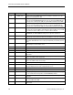
Address Descriptor Description
15 EMER STPT A value of the preset FLOW STPT, in percent, that the controller uses as the
setpoint when EMER ALM is ON.
16 LOW WARN This point displays an ON or OFF status. When the exhaust flow goes below the
value specified at LOW WARN LMT for the time specified in ALARM TIME, the
point goes into a warning state (ON); the yellow LED is illuminated at the ODP.
17 HIGH WARN This point displays an ON or OFF status. When the exhaust flow goes above the
value specified at HI WARN LMT for the time specified in ALARM TIME, the
point goes into a warning state (ON), the yellow LED is illuminated at the ODP.
19 ALM AKNLG This point displays an ON or OFF status that indicates the Horn Silence button
has been pressed at the ODP to acknowledge an alarm condition. The point will
reset when the alarm condition clears or another alarm is initiated.
27 AO2 DEADBAND When EXH FLOW and FLOW STPT are different by more than the AO2
DEADBAND, the AO2 FLOW SIG changes from setpoint to actual flow.
30 AO2 RANGE Scaling for the Analog Output (AO2) point. To get the correct output, the slope
and intercept of this point must match the point database of the room controller.
34 TRANS RANGE The maximum range, in inches of water (PA), of the differential pressure
transmitter. Standard values are 0.1 (25.3), 0.25 (62.275), 0.5 (124.55), and 1.0
(253).
35 EXH FLOW The calculated value, in CFM (LPS), of the exhaust airflow as measured with the
differential pressure transmitter sensor.
36 FLOW COEFF Gain factor for the flow sensor.
37 FLOW STPT Setpoint, in CFM (LPS), that the airflow is controlled to.
38 FLOW LO STPT The low flow setpoint used in FLOW STPT.
40 CAL DP TRANS YES or NO point used to calibrate the zero point of the differential pressure
transmitter.
41 DO1 SUP Digital output 1 is used to control the analog output-pneumatic (AO-P) supply
valve or the AO-E module supply input.
42 DO2 EXH Digital output 2 is used to control the analog output-pneumatic (AO-P) exhaust
valve or the AO-E module exhaust input.
43 DO3 Digital output 3 is a spare output.
44 AI1 DP TRANS Analog input 1, a 4 to 20 mA signal from the differential pressure transmitter.
The point displays the mA value of input from the sensor.
45 AI2 0.10V Analog input 2 is a 0 to 10 Vdc spare input.
46 AO1 0.10V Spare analog output is a 0 to 10 Vdc output.
47 AO2 FLOW SIG
Analog output 2 signal is used to indicate the exhaust flow setpoint. The output
is 1 to 10 Vdc, which corresponds to 0 to A02 RANGE (Point 30).
48 DI1 STPT SW Digital input for dry contact connection to control the HI/LOW flow setpoint of the
controller.
54 ODP DISPLAY Controls the function of the ODP display. It will display either CFM divided by
10 or HI FLOW / LO FLOW.
55 DO3 MODE Controls the function of the DO3. It will follow either the HI/LO setpoint or the
alarm status.