
Commissioning Instructions


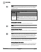
Table Of Contents
- Before You Begin
- Verifying Power
- Verifying Slave Mode Application Number
- Setting Controller Address
- Setting the Application
- Setting Display Units
- Testing the Operator Display Panel
- Setting Duct Area
- Setting Airflow Sensing Input
- Setting Flow Coefficients
- Automatic Calibration Option
- Setting Blank Display
- Setting Display Weight
- Setting Display Resolution
- Changing Exhaust Minimum
- Changing Exhaust Maximum
- Changing Face Velocity Setpoints and OCC Delay
- Setting Hi and Low Warn Limits
- Setting Hi and Low Alarm Limits
- Setting Alarm Timer
- Setting Emergency Setpoint
- Setting Emergency Timer
- Setting Remote Purge
- Fume Hood Specific Sash Setup and Calibration
- Setting External Face Area Input
- Setting Sash Area Alarms
- (Optional) Setting Damper Control — Application 2941
- Checkout of Damper — Application 2941
- (Optional) Setting Airflow Input Type
- (Optional) Calibrating the DP Transmitter without an Autozero Module
- (Optional) Calibrating with an Autozero Module
- AVS FAILMODE
- Setting Airflow Control — Application 2942
- Range of Airflow Control — Application 2942
- Configuring Airflow Control — Application 2942
- Setting AO2 Range
- Setting AO2 Voltage Minimum
- Start-up/Decommission Mode
- Loop Tuning Procedures
- Flashing Controller Firmware

Before You Begin
Setting Blank Display
10
Siemens Industry, Inc. Start-up Procedures 140-1321
Restricted 2015-11-04
NOTE:
The air velocity sensor should be calibrated at least once every 24 hours. Make sure
that the sensor has been calibrated before balancing takes place, as this will affect
the balancer’s results.
CAL SETUP Options.
CAL SETUP
Option Values
Description
0 Calibration occurs ONLY when CAL AIR is set to YES.
1 Calibration occurs with an occupied to unoccupied mode changeover.
4
(factory default
mode)
Calibration occurs on the time interval set in CAL TIMER.
Example:
If CAL TIMER = 12, then the calibration period is 12 hours. In this
option, actual calibration is subject to a time delay of up to 10 minutes to
prevent it from interfering with a response to fume hood flow change(s).
This is the recommended option when using a controller with an Autozero
Module.
Setting Blank Display
Set BLANK DSPLY to NO in order to display airflow readings at the ODP.
NOTE:
If BLANK DSPLY is set to YES, alarms will still display at the ODP.
Setting Display Weight
Set DISPLAY WT to a value of 0 through 100% (default is 100%). The suggested value
is 30%.
NOTE:
If DISPLAY WT is set to 100%, the face velocity displayed at the ODP may fluctuate
rapidly. This rapid fluctuation is due to the constant adjustments of the FHC. When
DISPLAY WT is set to a value less than 100%, the face velocity displayed at the ODP
is a weighted calculated value. This value is used to stabilize the ODP displayed
value only; it has no effect on the control sequence.
If you set DISPLAY WT to zero, the Operator Display Panel will “freeze” at the last
read value. Setting DISPLAY WT to a value other than zero (suggested value is 30%)
allows the Operator Display Panel to update the displayed face velocity.
Setting Display Resolution
Set DISPLAY RES to a value of 0 through 255 fpm (0 to 1.3 m/s). The default is 5 fpm
(0.025 m/s). This value is used as a COV limit for face velocity readings displayed at
the ODP only; it has no affect on the control sequence and has no effect on values
going across the network.