
Commissioning Instructions
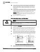
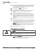
Table Of Contents
- Before You Begin
- Verifying Power
- Verifying Slave Mode Application Number
- Setting Controller Address
- Setting the Application
- Setting Display Units
- Testing the Operator Display Panel
- Setting Duct Area
- Setting Airflow Sensing Input
- Setting Flow Coefficients
- Automatic Calibration Option
- Setting Blank Display
- Setting Display Weight
- Setting Display Resolution
- Changing Exhaust Minimum
- Changing Exhaust Maximum
- Changing Face Velocity Setpoints and OCC Delay
- Setting Hi and Low Warn Limits
- Setting Hi and Low Alarm Limits
- Setting Alarm Timer
- Setting Emergency Setpoint
- Setting Emergency Timer
- Setting Remote Purge
- Fume Hood Specific Sash Setup and Calibration
- Setting External Face Area Input
- Setting Sash Area Alarms
- (Optional) Setting Damper Control — Application 2941
- Checkout of Damper — Application 2941
- (Optional) Setting Airflow Input Type
- (Optional) Calibrating the DP Transmitter without an Autozero Module
- (Optional) Calibrating with an Autozero Module
- AVS FAILMODE
- Setting Airflow Control — Application 2942
- Range of Airflow Control — Application 2942
- Configuring Airflow Control — Application 2942
- Setting AO2 Range
- Setting AO2 Voltage Minimum
- Start-up/Decommission Mode
- Loop Tuning Procedures
- Flashing Controller Firmware

Before You Begin
Changing Exhaust Minimum
11
Siemens Industry, Inc. Start-up Procedures 140-1321
Restricted 2015-11-04
NOTE:
If you set DISPLAY RES to zero, the Operator Display Panel will “freeze” at the face
velocity setpoint FVEL STPT. Resetting DISPLAY RES to a value other than zero
displays the face velocity incrementally. The factory default is 5, fpm values display in
increments of 5. For example, 80, 85, 90, 95, 100, and so on. If the actual filtered fpm
is 84, 85 will be displayed.
Changing Exhaust Minimum
The actual value for this point should be found on a schedule included with the
mechanical drawings for the job or from the Siemens job submittal.
The value of EXH MIN should be changed to a flow minimum as desired.
NOTE:
When controlling at a duct velocity less than 350 fpm (1.778 m/s), duct velocity
measurement errors will increase.
The equation relating airflow to air velocity is: Airflow (cfm) to Velocity (fpm) × Duct
Area (sq. ft.) × Flow Coefficient.
For best results: Airflow ÷ (Duct Area × Flow Coefficient) should be > 350.
Example
FLOW MIN ÷ [DUCT AREA × FLO COEF] > 350
Changing Exhaust Maximum
The actual value for this point should be found on a schedule included with the
mechanical drawings for the job or from the Siemens job submittal.
The default EXH MAX is 3500 cfm (1651.65 lps). The value of EXH MAX should be
changed flow maximum as desired.
NOTE:
Do not use a duct velocity less than 350 fpm (1.778 m/s), duct velocity measurement
errors will occur at duct velocities less than 350 fpm (1.778 m/s).
The equation relating airflow to air velocity is: Airflow (cfm) to Velocity (fpm) × Duct
Area (sq. ft.) × Flow Coefficient.