
Commissioning Instructions
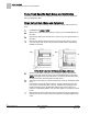
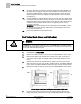
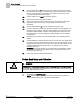
Table Of Contents
- Before You Begin
- Verifying Power
- Verifying Slave Mode Application Number
- Setting Controller Address
- Setting the Application
- Setting Display Units
- Testing the Operator Display Panel
- Setting Duct Area
- Setting Airflow Sensing Input
- Setting Flow Coefficients
- Automatic Calibration Option
- Setting Blank Display
- Setting Display Weight
- Setting Display Resolution
- Changing Exhaust Minimum
- Changing Exhaust Maximum
- Changing Face Velocity Setpoints and OCC Delay
- Setting Hi and Low Warn Limits
- Setting Hi and Low Alarm Limits
- Setting Alarm Timer
- Setting Emergency Setpoint
- Setting Emergency Timer
- Setting Remote Purge
- Fume Hood Specific Sash Setup and Calibration
- Setting External Face Area Input
- Setting Sash Area Alarms
- (Optional) Setting Damper Control — Application 2941
- Checkout of Damper — Application 2941
- (Optional) Setting Airflow Input Type
- (Optional) Calibrating the DP Transmitter without an Autozero Module
- (Optional) Calibrating with an Autozero Module
- AVS FAILMODE
- Setting Airflow Control — Application 2942
- Range of Airflow Control — Application 2942
- Configuring Airflow Control — Application 2942
- Setting AO2 Range
- Setting AO2 Voltage Minimum
- Start-up/Decommission Mode
- Loop Tuning Procedures
- Flashing Controller Firmware

Before You Begin
Changing Face Velocity Setpoints and OCC Delay
12
Siemens Industry, Inc. Start-up Procedures 140-1321
Restricted 2015-11-04
Changing Face Velocity Setpoints and OCC Delay
Most jobs require a single face velocity setpoint of 100 fpm (0.05 m/s). If this fume
hood has more than one setpoint required, then perform the steps, otherwise skip this
section.
1.
Change Report to
OCC.UNOCC
.
2.
Set OCC FV STPT and UNOCC FV STPT to the desired face velocities.
Values are in 1 fpm (0.005 m/s) increments. The defaults are 100 and 90
respectively. The default of 100 fpm (0.05 m/s) is the recognized industry
standard. When using lower values, verify that the hood still contains all the
fumes. Valid values are 0 through 255.
3.
Set OCC DELAY to the desired time delay between when OCC.UNOCC
changes to the UNOCC state and when the face velocity is changed to
UNOCC FV STPT. OCC.UNOCC is controlled by the DI, when it is in OCC
mode (DI open) the face velocity is controlled to OCC FV STPT and when it is
in UNOCC mode (DI closed) the face velocity is controlled to UNOCC FV
STPT. Values are in 1 fpm increments. Valid values are 0 to 255.
Face Velocity Setpoint Control
When there are multiple occupied face velocity setpoints, the ODP buttons can be
used to change between the different setpoints.
1. Enter values for OCC LOW FV, OCC FV STPT and OCC FV HIGH.
– Values must be entered in ascending order; non-ascending values will not be
accepted by the controller.
– Values that are the same are acceptable (that is, 100, 100).
2. Once the values are entered, you can change between the setpoints by pressing
the LEFT and RIGHT lower middle ODP buttons.
– When the left button is pushed, lower the face velocity setpoint (from high to
med or med to low).
– When the right button is pushed, raise the face velocity setpoint (from low to
med or med to high).
Setting Hi and Low Warn Limits
Skip this step unless there is a special requirement on the job; the default will be used.
1.
Change report to
STARTUP
.
2.
Set HI WARN LMT and LOW WARN LMT.
These limits are defined as a percentage of the controlled setpoint, meaning
that the alarm limits will be closer as the face velocity setpoint decreases. The
default values are 135% and 85% respectively. These points may be adjusted
to meet customer requirements.