
Commissioning Instructions
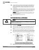
Table Of Contents
- Before You Begin
- Verifying Power
- Verifying Slave Mode Application Number
- Setting Controller Address
- Setting the Application
- Setting Display Units
- Testing the Operator Display Panel
- Setting Duct Area
- Setting Airflow Sensing Input
- Setting Flow Coefficients
- Automatic Calibration Option
- Setting Blank Display
- Setting Display Weight
- Setting Display Resolution
- Changing Exhaust Minimum
- Changing Exhaust Maximum
- Changing Face Velocity Setpoints and OCC Delay
- Setting Hi and Low Warn Limits
- Setting Hi and Low Alarm Limits
- Setting Alarm Timer
- Setting Emergency Setpoint
- Setting Emergency Timer
- Setting Remote Purge
- Fume Hood Specific Sash Setup and Calibration
- Setting External Face Area Input
- Setting Sash Area Alarms
- (Optional) Setting Damper Control — Application 2941
- Checkout of Damper — Application 2941
- (Optional) Setting Airflow Input Type
- (Optional) Calibrating the DP Transmitter without an Autozero Module
- (Optional) Calibrating with an Autozero Module
- AVS FAILMODE
- Setting Airflow Control — Application 2942
- Range of Airflow Control — Application 2942
- Configuring Airflow Control — Application 2942
- Setting AO2 Range
- Setting AO2 Voltage Minimum
- Start-up/Decommission Mode
- Loop Tuning Procedures
- Flashing Controller Firmware

Before You Begin
Setting Hi and Low Alarm Limits
13
Siemens Industry, Inc. Start-up Procedures 140-1321
Restricted 2015-11-04
Setting Hi and Low Alarm Limits
Skip this step unless there is a special requirement on the job; the default will be used.
1.
Change report to
STARTUP
.
2.
Set HI ALM LMT and LOW ALM LMT.
These limits are defined as a percentage of the controlled setpoint, meaning
that the alarm limits will be closer as the face velocity setpoint decreases.
The default values are 150% and 70% respectively. These points may be
adjusted to meet customer requirements.
Setting Alarm Timer
Skip this step unless there is a special requirement on the job; the default will be used.
Set ALARM TIME to a value of 1 through 255 seconds.
This is the time the flow must be in an alarm or warn condition before the alarm will
sound. The alarm clears immediately upon returning to normal operation. The
default for ALARM TIME is 5 seconds.
Setting Emergency Setpoint
Skip this step unless there is a special requirement on the job, the default will be used.
Set EMER STPT to a value of 0 through 255%; default value is 150%.
This percentage, multiplied by the face velocity setpoint, (or MIN FLOW in the
minimum flow condition), is used to set the fume hood to a safe operating level
during the second phase of the emergency purge sequence.
NOTE: If EMER STPT is set to a value less than 100%, the exhaust flow will be
reduced during the emergency purge sequence.
Setting Emergency Timer
Skip this step unless there is a special requirement on the job, the default will be used.
Set EMER TIMER to a value of 0 through 32,767 seconds; default is 300 seconds.
This is the time the fume hood will be at full exhaust during the first phase of the
emergency purge sequence.
NOTE: If EMER TIMER is set to zero, the FHC immediately sets the exhaust flow
to EMER STPT when the emergency purge button is pushed.
Setting Remote Purge
Skip this step unless there is a special requirement on the job, the default will be used.
Set EMER DI 6 to YES when it is desired to have the shorting of DI6 causing an
EMERGENCY PURGE of the fume hood.