
Commissioning Instructions
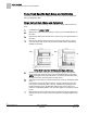
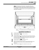
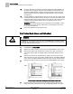
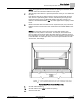
Table Of Contents
- Before You Begin
- Verifying Power
- Verifying Slave Mode Application Number
- Setting Controller Address
- Setting the Application
- Setting Display Units
- Testing the Operator Display Panel
- Setting Duct Area
- Setting Airflow Sensing Input
- Setting Flow Coefficients
- Automatic Calibration Option
- Setting Blank Display
- Setting Display Weight
- Setting Display Resolution
- Changing Exhaust Minimum
- Changing Exhaust Maximum
- Changing Face Velocity Setpoints and OCC Delay
- Setting Hi and Low Warn Limits
- Setting Hi and Low Alarm Limits
- Setting Alarm Timer
- Setting Emergency Setpoint
- Setting Emergency Timer
- Setting Remote Purge
- Fume Hood Specific Sash Setup and Calibration
- Setting External Face Area Input
- Setting Sash Area Alarms
- (Optional) Setting Damper Control — Application 2941
- Checkout of Damper — Application 2941
- (Optional) Setting Airflow Input Type
- (Optional) Calibrating the DP Transmitter without an Autozero Module
- (Optional) Calibrating with an Autozero Module
- AVS FAILMODE
- Setting Airflow Control — Application 2942
- Range of Airflow Control — Application 2942
- Configuring Airflow Control — Application 2942
- Setting AO2 Range
- Setting AO2 Voltage Minimum
- Start-up/Decommission Mode
- Loop Tuning Procedures
- Flashing Controller Firmware

Before You Begin
Fume Hood Specific Sash Setup and Calibration
18
Siemens Industry, Inc. Start-up Procedures 140-1321
Restricted 2015-11-04
12.
Set CAL SASH POS to
0
inches (minimum) unless a physical stop prevents
the sash from fully closing. If a physical stop is present, measure the distance
from the lower end of the vertical track to the bottom of the sash in inches
(cm). Set CAL SASH POS to this value.
13.
Set CAL SASH LOC to
MAX
for maximum opening.
14.
Open the sash to the fully opened position.
15.
Measure the distance from the lower end of the vertical track to the bottom
edge of the sash in inches (cm). Set CAL SASH POS to this value
(maximum).
16.
Set CAL SASH NUM to
0
to turn the calibration sequence OFF.
17.
Close the sash fully and verify that the value displayed at VERT SASH1 is at
the minimum set in Step 9. Open the sash half way and verify that the value
displayed at VERT SASH1 is equal to the measured value. Open the sash
fully and verify that the value displayed at VERT SASH1 is at the maximum
set in Step 12.
18.
Repeat Steps 10 through 18 for CAL SASH NUM = 2 for calibrating VERT
SASH2.
19.
Set FAIL AREA to a desired fail-safe value for the face area. The default value
is 0 square feet. This value is used in the event of a sash sensor failure as the
default face area opening. When a sash sensor fails, this value will be used to
calculate what the exhaust flow should be. It is typically set to 1/2 of the
maximum open area.
WARNING:
Pay careful attention to the value entered in FAIL AREA. A value
too low may not provide enough exhaust flow for safe operation of a Fume
Hood should a sensor fail.
20.
Proceed to
External Face Area Input Setup
.
Vertical Sash Setup and Calibration
WARNING
The application cannot detect a broken wire to the analog input for the second sash.
An external sash aggregating device should be used to calculate the face area for all
fume hoods with more than one sash.
1.
Set REPORT to
VERT WALKIN
.
NOTE:
Numbers on the sashes show how the sashes are wired. Sash 1 is
wired to VERT SASH1; Sash 2 is wired to VERT SASH2.