
Commissioning Instructions
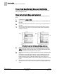
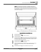
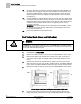
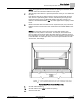
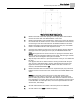
Table Of Contents
- Before You Begin
- Verifying Power
- Verifying Slave Mode Application Number
- Setting Controller Address
- Setting the Application
- Setting Display Units
- Testing the Operator Display Panel
- Setting Duct Area
- Setting Airflow Sensing Input
- Setting Flow Coefficients
- Automatic Calibration Option
- Setting Blank Display
- Setting Display Weight
- Setting Display Resolution
- Changing Exhaust Minimum
- Changing Exhaust Maximum
- Changing Face Velocity Setpoints and OCC Delay
- Setting Hi and Low Warn Limits
- Setting Hi and Low Alarm Limits
- Setting Alarm Timer
- Setting Emergency Setpoint
- Setting Emergency Timer
- Setting Remote Purge
- Fume Hood Specific Sash Setup and Calibration
- Setting External Face Area Input
- Setting Sash Area Alarms
- (Optional) Setting Damper Control — Application 2941
- Checkout of Damper — Application 2941
- (Optional) Setting Airflow Input Type
- (Optional) Calibrating the DP Transmitter without an Autozero Module
- (Optional) Calibrating with an Autozero Module
- AVS FAILMODE
- Setting Airflow Control — Application 2942
- Range of Airflow Control — Application 2942
- Configuring Airflow Control — Application 2942
- Setting AO2 Range
- Setting AO2 Voltage Minimum
- Start-up/Decommission Mode
- Loop Tuning Procedures
- Flashing Controller Firmware

Before You Begin
Fume Hood Specific Sash Setup and Calibration
19
Siemens Industry, Inc. Start-up Procedures 140-1321
Restricted 2015-11-04
Walk-In Vertical Sash Configurations.
2.
Measure the width of the sash opening in inches (cm). Both vertical sashes
must be the same width. Set VERT WIDTH1 to this value.
3.
Measure the full height of the vertical track in inches (cm). This is the distance
the vertical sash can travel in its track. If this value is different for both sashes,
use the longer of the two measurements. Set TRACK HEIGHT to this value.
4.
Measure the height of the individual sash panels in inches (cm). Set VSASH
HGHT1 and VSASH HGHT2 to their respective values.
5.
Open the sash until the top edge of the covers the bypass opening. Measure
the height of the sash opening in inches (cm). Set BYPASS HGHT to this
value.
NOTE:
The bypass area of the fume hood is an opening that increases when
the sash closes and decreases when the sash opens. See the Figure
Vertical
Sash Fume Hood with Bypass Area Open and Closed
.
6.
Skip this step unless there is a special requirement on the job - the default will
be used.
If the bypass area has an airflow restrictor covering and flush with the open
area, such as a perforated grille or louvers, estimate the percentage of the
bypass area that is open. Set BYPASS OPEN to this value. If there is no
restrictor, set BYPASS OPEN to
100
.
7.
Measure the fixed area of the fume hood in square feet (m2). Any fume hood
leakage must be accounted for in this measurement. Set FIXED AREA to this
value.
NOTE:
The fixed area of the fume hood is an area that remains open
regardless of sash position or movement. For example, most fume hoods
have an intake gap under the lower airfoil and above the cabinet of the fume
hood (typically a 1 inch gap). Also include 1% of the maximum open face area
in this calculation for other open areas, such as the space between the sash
and the track, and leakage.
8.
Set CAL SASH NUM to the number of the sash panel to be calibrated.
9.
Set CAL SASH LOC to
MIN
for minimum opening.