
Commissioning Instructions
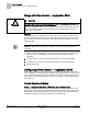
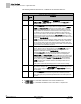
Table Of Contents
- Before You Begin
- Verifying Power
- Verifying Slave Mode Application Number
- Setting Controller Address
- Setting the Application
- Setting Display Units
- Testing the Operator Display Panel
- Setting Duct Area
- Setting Airflow Sensing Input
- Setting Flow Coefficients
- Automatic Calibration Option
- Setting Blank Display
- Setting Display Weight
- Setting Display Resolution
- Changing Exhaust Minimum
- Changing Exhaust Maximum
- Changing Face Velocity Setpoints and OCC Delay
- Setting Hi and Low Warn Limits
- Setting Hi and Low Alarm Limits
- Setting Alarm Timer
- Setting Emergency Setpoint
- Setting Emergency Timer
- Setting Remote Purge
- Fume Hood Specific Sash Setup and Calibration
- Setting External Face Area Input
- Setting Sash Area Alarms
- (Optional) Setting Damper Control — Application 2941
- Checkout of Damper — Application 2941
- (Optional) Setting Airflow Input Type
- (Optional) Calibrating the DP Transmitter without an Autozero Module
- (Optional) Calibrating with an Autozero Module
- AVS FAILMODE
- Setting Airflow Control — Application 2942
- Range of Airflow Control — Application 2942
- Configuring Airflow Control — Application 2942
- Setting AO2 Range
- Setting AO2 Voltage Minimum
- Start-up/Decommission Mode
- Loop Tuning Procedures
- Flashing Controller Firmware

Before You Begin
(Optional) Calibrating with an Autozero Module
23
Siemens Industry, Inc. Start-up Procedures 140-1321
Restricted 2015-11-04
3.
Set CAL AIR to
YES
. The calibration will take approximately 3 seconds. When
calibration is completed, this point will automatically change back to NO.
4.
When
CAL AIR
changes back to NO, reconnect the HI and the LO tubing to
the transmitter (or to the flow sensor if you disconnected it there).
(Optional) Calibrating with an Autozero Module
This section is for fume hoods with an external pressure sensor and an Autozero
module. If the DP Transmitter is slightly out of adjustment, you can compensate for that
within the controller.
1. Set REPORT to AIRFLOW IN.
2. Set CAL AIR to YES.
When calibration is completed, this point will automatically change back to NO.
AVS FAILMODE
AVS FAILMODE is a point that describes how the Venturi Air Valve will respond if the
Air Velocity Sensor (AVS1) fails.
Set AVS FAILMODE to the desired value.
AVS1 failure and AVS FAILMODE values.
AVS FAILMODE
OPEN
(default)
Exhaust fails Open
HOLD Exhaust Holds current Position
Setting Airflow Control — Application 2942
Refer to the chart below. If you have a setpoint that will fall below the value in this
chart, you must perform these steps; otherwise, these steps can be skipped.
Airflows below 350 fpm are difficult to sense precisely. If your valve will be operating
below 350 fpm (see the Table
Venturi Airflow @ 350 fpm
for the corresponding cfm),
perform the following steps.
Venturi Airflow @ 350 fpm
Valve Size in Inches
cfm
lps
6 69 32
8 122 58
10 191 90
12 275 130
Dual 10 380 174
Dual 12 550 259
Triple 12 825 389