
Commissioning Instructions
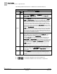
Table Of Contents
- Before You Begin
- Verifying Power
- Verifying Slave Mode Application Number
- Setting Controller Address
- Setting the Application
- Setting Display Units
- Testing the Operator Display Panel
- Setting Duct Area
- Setting Airflow Sensing Input
- Setting Flow Coefficients
- Automatic Calibration Option
- Setting Blank Display
- Setting Display Weight
- Setting Display Resolution
- Changing Exhaust Minimum
- Changing Exhaust Maximum
- Changing Face Velocity Setpoints and OCC Delay
- Setting Hi and Low Warn Limits
- Setting Hi and Low Alarm Limits
- Setting Alarm Timer
- Setting Emergency Setpoint
- Setting Emergency Timer
- Setting Remote Purge
- Fume Hood Specific Sash Setup and Calibration
- Setting External Face Area Input
- Setting Sash Area Alarms
- (Optional) Setting Damper Control — Application 2941
- Checkout of Damper — Application 2941
- (Optional) Setting Airflow Input Type
- (Optional) Calibrating the DP Transmitter without an Autozero Module
- (Optional) Calibrating with an Autozero Module
- AVS FAILMODE
- Setting Airflow Control — Application 2942
- Range of Airflow Control — Application 2942
- Configuring Airflow Control — Application 2942
- Setting AO2 Range
- Setting AO2 Voltage Minimum
- Start-up/Decommission Mode
- Loop Tuning Procedures
- Flashing Controller Firmware

Before You Begin
Configuring Airflow Control — Application 2942
27
Siemens Industry, Inc. Start-up Procedures 140-1321
Restricted 2015-11-04
If they pass (that is, if enough increment correctly), these new values become the
active values, and the old active values become inactive. However, if the new values
don’t pass, then the old active values remain active.
Running a successful calibration sequence is one way of changing or updating the
active values. You can also edit the table manually. Normally this is not necessary, but
if you are having flow control problems you may need to edit the table.
In order to manually edit the table statement, you must first know which points in the
active table need adjusting. This is done by setting V TABLE PT
to the appropriate
active point values found in Table
Venturi Air Valve Table Statement
in order to gather
and view the active voltage/flow curve for the Venturi Air Valve and its actuator. By
gathering and analyzing the active voltage/flow values (for example, you can plot them
on a graph as in Figure
Problematic Venturi Air Valve Voltage/Flow Curves
), you can
decide which one(s) need adjusting. The flow curve should be smooth and
incremental.
You can change the active values using the following steps:
1. Set V TABLE PT to a “swap” value that tells the application to exchange active
table values with inactive table values (see Table
Venturi Air Valve Table
Statement
for swap value).
This step is necessary because the application does not allow active values to
be manually overridden.
NOTE:
An exception to this rule is the first element in the active portion of the table—the low
flow point—can be edited directly. Table
Venturi Air Valve Table Statement
explains
this in more detail.
2. Edit the inactive table values.
Since you have just switched the active and inactive portions of the table in
Step 1, the inactive values are now identical to what the active values were
moments ago. You can now edit these new inactive values by using V TABLE
PT to reference them in TABLE FLOW and TABLE VOLTS. Table
Venturi Air
Valve Table Statement
explains this in more detail.
3. Set V TABLE PT once again to the swap value. This places the newly edited
inactive values back into the active portion of the table statement (again, the active
and inactive portions of the table are simply swapped). However, before the swap
is finalized, the application analyzes your proposed values using the same logic as
in a regular calibration sequence.
⇨ If your proposed values are good, then the swap is made and the edited
values are accepted into the active portion of the table. EXH VLV STAT
is set to CAL OK for exhaust calibration and control of the Venturi Air
Valve resumes.
⇨ However, if either point is set to NOTCAL, you must gather and view the
voltage/flow values to see where the problem lies.