
Commissioning Instructions
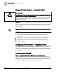
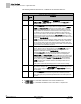
Table Of Contents
- Before You Begin
- Verifying Power
- Verifying Slave Mode Application Number
- Setting Controller Address
- Setting the Application
- Setting Display Units
- Testing the Operator Display Panel
- Setting Duct Area
- Setting Airflow Sensing Input
- Setting Flow Coefficients
- Automatic Calibration Option
- Setting Blank Display
- Setting Display Weight
- Setting Display Resolution
- Changing Exhaust Minimum
- Changing Exhaust Maximum
- Changing Face Velocity Setpoints and OCC Delay
- Setting Hi and Low Warn Limits
- Setting Hi and Low Alarm Limits
- Setting Alarm Timer
- Setting Emergency Setpoint
- Setting Emergency Timer
- Setting Remote Purge
- Fume Hood Specific Sash Setup and Calibration
- Setting External Face Area Input
- Setting Sash Area Alarms
- (Optional) Setting Damper Control — Application 2941
- Checkout of Damper — Application 2941
- (Optional) Setting Airflow Input Type
- (Optional) Calibrating the DP Transmitter without an Autozero Module
- (Optional) Calibrating with an Autozero Module
- AVS FAILMODE
- Setting Airflow Control — Application 2942
- Range of Airflow Control — Application 2942
- Configuring Airflow Control — Application 2942
- Setting AO2 Range
- Setting AO2 Voltage Minimum
- Start-up/Decommission Mode
- Loop Tuning Procedures
- Flashing Controller Firmware

Before You Begin
Configuring Airflow Control — Application 2942
28
Siemens Industry, Inc. Start-up Procedures 140-1321
Restricted 2015-11-04
The following table lists all values for V TABLE PT and describes their use.
Venturi Air Valve Table Statement
V
TABLE
PT
Description
0 Default value for
V TABLE PT
. When
V TABLE PT
equals 0, changes to
TABLE FLOW
or
TABLE VOLTS
are ignored. Setting
V TABLE PT
to 0
cancels an edit session.
Active
31
Setting
V TABLE PT
to 31 takes the flow (cfm) and voltage values from
the first element of the active supply table and displays them in
TABLE
FLOW
and
TABLE VOLTS
where they can be edited. (This is the only
active supply element (or “point”) that can be directly edited.) Flow and
voltage values are not allowed to exceed those in active supply point 32.
To operate in the range below minimum readable flow (less than 350
fpm), a low flow value in cfm from either the room schedule or the supply
Venturi Air Valve housing is entered into
TABLE FLOW
, with the correct
corresponding actuator voltage determined/confirmed by the balancer and
entered into
TABLE VOLTS
.
NOTE:
This point is only necessary for supply Venturi Air Valve operation
in the range below minimum readable flow (below 350 fpm). Otherwise it
can be ignored. This low flow point must be entered only after other non-
zero points exist in the table as a result of manual edits, or as the result of
a prior Venturi auto calibration sequence.
32 - 46 This portion of the table (32 through 46) can be viewed but not edited
directly. When a point is selected (that is, when
V TABLE PT
is set to a
value 2 through 16), the corresponding flow and voltage values are
displayed in TABLE FLOW and
TABLE VOLTS
.
Setting
V TABLE PT
to 32 will result in the smallest readable flow and
associated voltage for the supply Venturi Air Valve to be displayed in
TABLE FLOW
and
TABLE VOLTS; setting V TABLE PT to 46 will result in
the maximum flow and associated voltage for the supply Venturi Air Valve
to be displayed in TABLE
FLOW
and
TABLE VOLTS
. The in between
values (33 through 45) are for the range of flow between min and max.
NOTE:
The table swap will fail if valid flow and voltage values are not
entered in Point 46.
Table entries marked as failed display FAIL for both flow and voltage.
Inactive 91 – 106 This portion of the table can be viewed and edited. By entering a point
(any value 91 through 106)
into V TABLE PT
, the corresponding cfm and
voltage values display in
TABLE FLOW
and
TABLE VOLTS
where they
can be edited.
Swap 121 Setting
V TABLE PT
to 121 instructs the controller to evaluate the values
in the inactive portion of the table using standard calibration pass/fail
logic. If they pass, they are exchanged with those in the active portion of
the table.
If FLOW COEF is 0, the table edit feature uses a flow coefficient of 1.
If DUCT AREA is 0, the table edit feature uses a duct area of 1 square foot.