
Commissioning Instructions
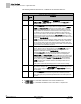
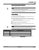

Table Of Contents
- Before You Begin
- Verifying Power
- Verifying Slave Mode Application Number
- Setting Controller Address
- Setting the Application
- Setting Display Units
- Testing the Operator Display Panel
- Setting Duct Area
- Setting Airflow Sensing Input
- Setting Flow Coefficients
- Automatic Calibration Option
- Setting Blank Display
- Setting Display Weight
- Setting Display Resolution
- Changing Exhaust Minimum
- Changing Exhaust Maximum
- Changing Face Velocity Setpoints and OCC Delay
- Setting Hi and Low Warn Limits
- Setting Hi and Low Alarm Limits
- Setting Alarm Timer
- Setting Emergency Setpoint
- Setting Emergency Timer
- Setting Remote Purge
- Fume Hood Specific Sash Setup and Calibration
- Setting External Face Area Input
- Setting Sash Area Alarms
- (Optional) Setting Damper Control — Application 2941
- Checkout of Damper — Application 2941
- (Optional) Setting Airflow Input Type
- (Optional) Calibrating the DP Transmitter without an Autozero Module
- (Optional) Calibrating with an Autozero Module
- AVS FAILMODE
- Setting Airflow Control — Application 2942
- Range of Airflow Control — Application 2942
- Configuring Airflow Control — Application 2942
- Setting AO2 Range
- Setting AO2 Voltage Minimum
- Start-up/Decommission Mode
- Loop Tuning Procedures
- Flashing Controller Firmware

Before You Begin
Setting AO2 Voltage Minimum
31
Siemens Industry, Inc. Start-up Procedures 140-1321
Restricted 2015-11-04
NOTE:
AO2 DEADBAND can be set from 0 to 102% in 0.4% increments. 0% will give the
actual flow all the time. This signal may be too bouncy to give a stable output and will
cause short-term room instability during fume hood sash movements. A 10%
deadband is equal to ±5% of the flow. Any value over 100% will turn the feature off
and revert to standard control.
For stable pressure reading, lower the AO2 DEADBAND. For unstable pressure
readings, raise the AO2 DEADBAND until the output signal stabilizes.
Setting AO2 Voltage Minimum
This section can be skipped, if the FHC is connected to a room controller or field panel
from Siemens Industry, Inc.
This function allows the minimum voltage to be set to a value other than 1 (default).
The minimum voltage is output when the flow is equal to 0 cfm.
Set AO2 V MIN to the desired value.
Start-up/Decommission Mode
The Fume Hood Controller contains different modes controlled by STARTUP MODE
(default is 3). These modes of operation allow the controller to be started up without
the sound of nuisance alarms at the hood. These modes are useful at different stages
of construction and after decommissioning.
The FHC also contains decommission modes and allow some or all of the functionality
of the controller to be turned off.
The modes are described as an enumerated point:
STARTUP MODE
Mode
Description
0 Normal The controller is fully functional.
1 Decommission The controller is fully functional, except the flow
setpoint is set to 0, alarming is limited and the ODP
displays “Out of service” and “OFF”. If the sash is
opened, control is returned and you are notified that
the hood is “Out of service”.
2 Non-functional
Decommission,
closed
The controller is fully functional, except the flow
setpoint is set to 0, alarming is limited and the ODP
displays “Out of service” and “OFF”. If the sash is
opened, nothing changes.
3
(default)
Non-functional
Startup
The controller is fully functional, except alarming does
not work and the ODP displays “Controller – Startup”
and “OFF”.
To enter modes 1 and 2, the fume hood sashes must be in the closed position, and
FACE AREA must be smaller than UN ALRT AREA.
The digital output DO6 can be used for local indication that the sash was opened after
the hood entered Out of Service mode. The output will remain ON until STARTUP
MODE is changed.