
Commissioning Instructions
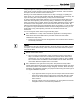
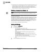
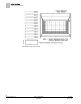

Table Of Contents
- Before You Begin
- Verifying Power
- Verifying Slave Mode Application Number
- Setting Controller Address
- Setting the Application
- Setting Display Units
- Testing the Operator Display Panel
- Setting Duct Area
- Setting Airflow Sensing Input
- Setting Flow Coefficients
- Automatic Calibration Option
- Setting Blank Display
- Setting Display Weight
- Setting Display Resolution
- Changing Exhaust Minimum
- Changing Exhaust Maximum
- Changing Face Velocity Setpoints and OCC Delay
- Setting Hi and Low Warn Limits
- Setting Hi and Low Alarm Limits
- Setting Alarm Timer
- Setting Emergency Setpoint
- Setting Emergency Timer
- Setting Remote Purge
- Fume Hood Specific Sash Setup and Calibration
- Setting External Face Area Input
- Setting Sash Area Alarms
- (Optional) Setting Damper Control — Application 2941
- Checkout of Damper — Application 2941
- (Optional) Setting Airflow Input Type
- (Optional) Calibrating the DP Transmitter without an Autozero Module
- (Optional) Calibrating with an Autozero Module
- AVS FAILMODE
- Setting Airflow Control — Application 2942
- Range of Airflow Control — Application 2942
- Configuring Airflow Control — Application 2942
- Setting AO2 Range
- Setting AO2 Voltage Minimum
- Start-up/Decommission Mode
- Loop Tuning Procedures
- Flashing Controller Firmware

Before You Begin
Loop Tuning Procedures
32
Siemens Industry, Inc. Start-up Procedures 140-1321
Restricted 2015-11-04
Loop Tuning Procedures
Set REPORT to TUNING.
General Information
The FHC uses one Proportional, Integral, and Derivative (PID) loop. It is similar to the
LOOP in a PPCL statement except gains are smaller by a factor of 1000. The process
variable (PV) is EXH VOL. The setpoint is EXH STPT. The control variable (CV) is
DMPR CMD.
You can evaluate loop performance and do loop tuning by observing the display at the
Operator’s Display Panel. The displayed face velocity is related to the exhaust flow,
which is directly controlled by the loop.
However, the most reliable way to evaluate loop performance is to collect trend data on
the exhaust volume and the exhaust setpoint.
When using the Operator Display Panel for loop evaluation or tuning, set DISPLAY WT
to 100%.
Loop Time
Commanding LOOP TIME controls the speed of the loop calculations. The value of
LOOP TIME controls how often the loop calculations are performed. The default value
is 0.1 seconds and can be increased to slow the response of the system.
Steady State Performance
Steady state performance is the ability of the loop to maintain its setpoint. Variation of
the EXH VOL from setpoint (with the sash position fixed) can be a sign of poor loop
tuning. However, if the exhaust flow measurement is very noisy, even with a perfectly
tuned loop, the exhaust volume display may still fluctuate.
To distinguish measurement noise from control loop hunting, set the DMPR CMD
output to a fixed value (0%). This locks the actuator; any remaining variation is
probably measurement noise.
Remember to release DMPR CMD when you are done.
Dynamic Performance
Dynamic performance is the speed and the overshoot involved in the response of the
face velocity to a movement of the sash. The face velocity display should return to
within 10% of the setpoint in three seconds or less with minimal overshoot.
Setting P-Gain
The loop should work well with P-only control. For any steady-state flow, the loop
output settles at 0% to maintain the actuator at a fixed position.
Trial and Error Method
If the loop responds too slowly to sash movement, double the EXH P GAIN and
reevaluate it.
If the face velocity overshoots a lot or swings back and forth after a sash movement,
decrease the EXH P GAIN and reevaluate it again.