
Commissioning Instructions
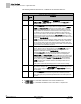
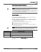
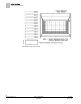

Table Of Contents
- Before You Begin
- Verifying Power
- Verifying Slave Mode Application Number
- Setting Controller Address
- Setting the Application
- Setting Display Units
- Testing the Operator Display Panel
- Setting Duct Area
- Setting Airflow Sensing Input
- Setting Flow Coefficients
- Automatic Calibration Option
- Setting Blank Display
- Setting Display Weight
- Setting Display Resolution
- Changing Exhaust Minimum
- Changing Exhaust Maximum
- Changing Face Velocity Setpoints and OCC Delay
- Setting Hi and Low Warn Limits
- Setting Hi and Low Alarm Limits
- Setting Alarm Timer
- Setting Emergency Setpoint
- Setting Emergency Timer
- Setting Remote Purge
- Fume Hood Specific Sash Setup and Calibration
- Setting External Face Area Input
- Setting Sash Area Alarms
- (Optional) Setting Damper Control — Application 2941
- Checkout of Damper — Application 2941
- (Optional) Setting Airflow Input Type
- (Optional) Calibrating the DP Transmitter without an Autozero Module
- (Optional) Calibrating with an Autozero Module
- AVS FAILMODE
- Setting Airflow Control — Application 2942
- Range of Airflow Control — Application 2942
- Configuring Airflow Control — Application 2942
- Setting AO2 Range
- Setting AO2 Voltage Minimum
- Start-up/Decommission Mode
- Loop Tuning Procedures
- Flashing Controller Firmware

Before You Begin
Loop Tuning Procedures
33
Siemens Industry, Inc. Start-up Procedures 140-1321
Restricted 2015-11-04
Face Velocity Accuracy Verification
This section presents the steps for verifying the face velocity accuracy.
NOTE:
It is recommended that this procedure be performed with the balancer so that the flow
coefficient is coordinated with the measured face velocity.
If hood performance verification is required for job completion, use Siemens Industry,
Inc.
Form Number 2396 Fume Hood Performance Test Report
. Complete all or part of
the form in accordance with the job requirements.
Vertical Sashes
Verify the face velocity as follows:
1. Move the sash to the fully opened position. If there is more than one sash, the
other sashes must be in the closed position.
2. Using a hand-held air velocity meter, perform a grid measurement of the face
velocity. (Divide the face of the fume hood into 1’ × 1’ squares.) Calculate the
average face velocity. See Figure 15.
3. Move the sash so that it is half open and repeat Steps 1 and 2.
4. Repeat Steps 1 through 3 for the remaining sashes.
5. Verify that the measured face velocity for each sash is within 10% of the face
velocity setpoint, FVEL STPT.
NOTE:
If the face velocity accuracy does not verify accordingly with the previous sash tests,
check to see that only the following points are set given the desired setup:
Sash Specific Setup
Operator Defined Points
All BYPASS HGHT; BYPASS OPEN; FIXED AREA; EXTERNAL A, FAIL AREA
Single Vertical VSASH HGHT1; TRACK HEIGHT; VERT WIDTH1
Vertical Floor-mounted VSASH HGHT1; VSASH HGHT2; TRACK HEIGHT; VERT WIDTH1
Dual Vertical V SASH HGHT1; V SASH HGHT2; TRACK HEIGHT; VERT WIDTH1, VERT
WIDTH2
Start-up is now complete. Set STARTUP MODE to 0, to enable the FHCs full
functionality.