
Commissioning Instructions


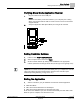
Table Of Contents
- Before You Begin
- Verifying Power
- Verifying Slave Mode Application Number
- Setting Controller Address
- Setting the Application
- Setting Display Units
- Testing the Operator Display Panel
- Setting Duct Area
- Setting Airflow Sensing Input
- Setting Flow Coefficients
- Automatic Calibration Option
- Setting Blank Display
- Setting Display Weight
- Setting Display Resolution
- Changing Exhaust Minimum
- Changing Exhaust Maximum
- Changing Face Velocity Setpoints and OCC Delay
- Setting Hi and Low Warn Limits
- Setting Hi and Low Alarm Limits
- Setting Alarm Timer
- Setting Emergency Setpoint
- Setting Emergency Timer
- Setting Remote Purge
- Fume Hood Specific Sash Setup and Calibration
- Setting External Face Area Input
- Setting Sash Area Alarms
- (Optional) Setting Damper Control — Application 2941
- Checkout of Damper — Application 2941
- (Optional) Setting Airflow Input Type
- (Optional) Calibrating the DP Transmitter without an Autozero Module
- (Optional) Calibrating with an Autozero Module
- AVS FAILMODE
- Setting Airflow Control — Application 2942
- Range of Airflow Control — Application 2942
- Configuring Airflow Control — Application 2942
- Setting AO2 Range
- Setting AO2 Voltage Minimum
- Start-up/Decommission Mode
- Loop Tuning Procedures
- Flashing Controller Firmware

4
Siemens Industry, Inc. Start-up Procedures 140-1321
Restricted 2015-11-04
Calibrating the Venturi Air Valves (Modes 1, 3) ................................................. 25
Low Flow Operation - Below 350 fpm (Mode 1) ................................................. 25
Editing the Venturi Table (Modes 1, 3) ............................................................... 26
PID Loop Only Operation (Mode 2) .................................................................... 29
Open Loop Operation (Mode 3) ......................................................................... 29
Tuning the Flow Loops (Mode 1, 2) .................................................................... 29
Stabilizing Unsteady Control (Mode 1, 2) ........................................................... 30
Setting AO2 Range ............................................................................................................ 30
Setting AO2 Voltage Minimum ........................................................................................... 31
Start-up/Decommission Mode ........................................................................................... 31
Loop Tuning Procedures ................................................................................................... 32
General Information ............................................................................................ 32
Loop Time ........................................................................................................... 32
Steady State Performance ................................................................................. 32
Dynamic Performance ........................................................................................ 32
Setting P-Gain .................................................................................................... 32
Trial and Error Method........................................................................................ 32
Face Velocity Accuracy Verification ................................................................... 33
Vertical Sashes ................................................................................................... 33
Flashing Controller Firmware ............................................................................................. 35