
Commissioning Instructions


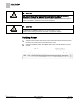
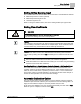
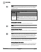
Table Of Contents
- Before You Begin
- Verifying Power
- Verifying Slave Mode Application Number
- Setting Controller Address
- Setting the Application
- Setting Display Units
- Testing the Operator Display Panel
- Setting Duct Area
- Setting Airflow Sensing Input
- Setting Flow Coefficients
- Automatic Calibration Option
- Setting Blank Display
- Setting Display Weight
- Setting Display Resolution
- Changing Exhaust Minimum
- Changing Exhaust Maximum
- Changing Face Velocity Setpoints and OCC Delay
- Setting Hi and Low Warn Limits
- Setting Hi and Low Alarm Limits
- Setting Alarm Timer
- Setting Emergency Setpoint
- Setting Emergency Timer
- Setting Remote Purge
- Fume Hood Specific Sash Setup and Calibration
- Setting External Face Area Input
- Setting Sash Area Alarms
- (Optional) Setting Damper Control — Application 2941
- Checkout of Damper — Application 2941
- (Optional) Setting Airflow Input Type
- (Optional) Calibrating the DP Transmitter without an Autozero Module
- (Optional) Calibrating with an Autozero Module
- AVS FAILMODE
- Setting Airflow Control — Application 2942
- Range of Airflow Control — Application 2942
- Configuring Airflow Control — Application 2942
- Setting AO2 Range
- Setting AO2 Voltage Minimum
- Start-up/Decommission Mode
- Loop Tuning Procedures
- Flashing Controller Firmware

Before You Begin
Verifying Power
5
Siemens Industry, Inc. Start-up Procedures 140-1321
Restricted 2015-11-04
Before You Begin
WARNING
A fume hood is a safety device.
Anyone attempting to start up a Fume Hood Controller and its related equipment
should have completed Operations Training.
Generic Controller I/O Layout. See Wiring Diagram for application specific details.
At the job site, locate the major control system and the mechanical and electrical
drawings. These components include valves, motors, and any other components
working in conjunction with the Fume Hood Controller (FHC).
Verify that the FHC input/output (I/O) points are wired per the installation instructions.
NOTE:
You should read and understand the sections on Venturi Air Valve Calibration and
Table Statement Editing in the
Application Note
documentation for Applications 2942
and/or 2941 before performing the Start-up Procedures. This is especially important if
you need to edit the Venturi table statement during start-up.
Venturi Air Valve for
Critical Environments Technical Specification Sheet
(149-425), has extensive
information regarding Venturi air valves for critical environments.
Offboard Air Module Wiring.