
Commissioning Instructions


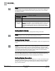
Table Of Contents
- Before You Begin
- Verifying Power
- Verifying Slave Mode Application Number
- Setting Controller Address
- Setting the Application
- Setting Display Units
- Testing the Operator Display Panel
- Setting Duct Area
- Setting Airflow Sensing Input
- Setting Flow Coefficients
- Automatic Calibration Option
- Setting Blank Display
- Setting Display Weight
- Setting Display Resolution
- Changing Exhaust Minimum
- Changing Exhaust Maximum
- Changing Face Velocity Setpoints and OCC Delay
- Setting Hi and Low Warn Limits
- Setting Hi and Low Alarm Limits
- Setting Alarm Timer
- Setting Emergency Setpoint
- Setting Emergency Timer
- Setting Remote Purge
- Fume Hood Specific Sash Setup and Calibration
- Setting External Face Area Input
- Setting Sash Area Alarms
- (Optional) Setting Damper Control — Application 2941
- Checkout of Damper — Application 2941
- (Optional) Setting Airflow Input Type
- (Optional) Calibrating the DP Transmitter without an Autozero Module
- (Optional) Calibrating with an Autozero Module
- AVS FAILMODE
- Setting Airflow Control — Application 2942
- Range of Airflow Control — Application 2942
- Configuring Airflow Control — Application 2942
- Setting AO2 Range
- Setting AO2 Voltage Minimum
- Start-up/Decommission Mode
- Loop Tuning Procedures
- Flashing Controller Firmware

Before You Begin
Verifying Slave Mode Application Number
7
Siemens Industry, Inc. Start-up Procedures 140-1321
Restricted 2015-11-04
Verifying Slave Mode Application Number
1.
Plug the cable into the micro USB port.
NOTE:
Drivers for the ODP II port must be loaded to your computer prior to being
able to communicate with the ODP II. Drivers can be found on the Technical
Support Website.
2.
Verify that Application 2900 (Slave Mode) is running at the controller.
Setting Controller Address
1.
In WCIS, select
View > Edit/View Reports
.
2.
Select a report from the list and click
Apply
.
3.
Set the controller address by setting CTLR ADDRESS to the appropriate
number. (Addresses 00 through 98 are valid; 00 through 31 are typically used.)
NOTE:
Update each controller at the field panel immediately after you complete the controller
start-up procedures and have made all other changes to the controller’s point
database (including balancing, tuning, and so on.)
Setting the Application
1.
Add the controller to your job database and select the desired application.
2900 Slave Mode
2941 with 2 Vertical Sash Sensors with Damper
2942 with 2 Vertical Sash Sensors with Venturi Air Valve
At the start of the calibration cycle, the controller automatically sets CAL AIR to YES.
When the cycle is complete, CAL AIR returns to NO.