
Installation Instructions

Document No. 546-14406
Installation Instructions
August 16, 2013
Page 2 of 8 Siemens Industry, Inc.
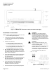
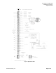
Figure 1. LCM-OAVS with Two Venturi Air Valves (One Exhaust, One Supply).
Installation Instructions
NOTE: Follow all safety regulations and local codes
when installing this equipment.
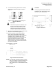
1. Using the mounting rail as a template (Figure
1), mark the screw holes where you will install
the LCM-OAVS.
2. Do one of the following:
• If using self-tapping screws, fasten the
mounting rail using a drill and hex nut bit.
• If not using self-tapping screws, drill two 1/8-
inch (3 mm) pilot holes, then fasten the
mounting rail with No. 6 or No. 8 screws.
3. With the ESD wrist strap attached to your wrist
and a good earth ground, remove the controller
from the anti-static bag and snap it securely into
place on the mounting rail.
4. If the LCM-OAVS will be used with a field panel,
disconnect the field level network (FLN) trunk
from the field panel.
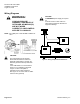
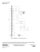
5. Wire the FLN trunk to the LCM-OAVS (Figure 2).
After all controllers are connected to the FLN,
reconnect the FLN trunk to the field panel.
6. If the LCM-OAVS requires Offboard Air
Modules, install them now following the
Installation Instructions (550-819).
7. Connect the point wiring. See Wiring Diagrams.
CAUTION:
DO Wiring – Each DO provides a
Normally Open (NO) terminal and a
Common (C) terminal. To reduce noise
and the potential for ground loops, both
connections of a 24 Vac load must be
wired directly to the DO terminals on the
controller board.
CAUTION:
DOs control 24 Vac loads only. The
maximum rating is 12 VA for each DO.
Use an interposing 220V
relay module for VA requirements higher
than the maximum, 110 or 220 Vac
requirements, DC power requirements,
or whenever a separate transformer is
used to power the load (540-147).
Figure 2. FLN Trunk Wiring.