
Installation Instructions

Document No. 546-14406
Installation Instructions
August 16, 2013
Siemens Industry, Inc. Page 3 of 6
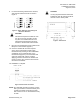
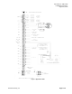
8. For each Fast Acting Lab Electronic Actuator,
verify that the switches are set as shown in
Figure 3:
Supply Exhaust
Figure 3. Switch Setting for Fast Acting Lab
Electronic Actuation.
CAUTION:
This actuator requires a maximum of 20
VA, 24 Vac source. DO NOT connect
any other non-isolated devices to the
transformer that powers the electronic
actuator or the hot water valve actuator.
9. Plug the room temperature sensor cable into the
RTS port on the controller (Figure 1).
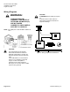
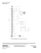
10. Connect a certified 24 Vac Class II power
source to the LCM-OAVS’s power supply
terminal block by inserting a 1/8-inch flat blade
screwdriver into a rectangular slot on the
terminal block (Figure 4). The screwdriver will
come into contact with a lever. Continue
applying pressure until the lever releases and
moves out of the way. Insert the wire and then
remove the screwdriver.
The installation is complete.
Figure 4. Power trunk connection.
NOTE: As a standard grounding procedure, ensure
that a ground wire is connected directly from
neutral of the 24Vac secondary (the side
that connects to the "C" terminal of the TEC)
to earth.
CAUTION:
It is very important that the neutral that
supplies the TEC be earth grounded at
the source of the 24Vac power.
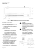
Figure 5. Dimensions.