
Installation Instructions

Document No. 546-14406
Installation Instructions
August 16, 2013
Page 4 of 6 Siemens Industry, Inc.
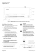
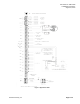
Wiring Diagrams
WARNING:
LCM-OAVS WILL BE
DAMAGED / DESTROYED IF
OFFBOARD AIR MODULE(S)
ARE NOT WIRED
CORRECTLY AND POWER IS
APPLIED TO LCM-OAVS.
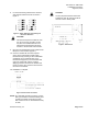
NOTE: For OAMs prior to 3/09 “O G P” is labeled as
“S + -“.
CAUTION:
The LCM-OAVS has two terminal
blocks with terminations numbered
identically (terminations 1 through 16).
DO NOT get these mixed up with each
other.
If the LCM-OAVS is not connected as
shown, it is not resistant to electrical
surges. It is also susceptible to
interference from other equipment.
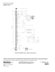
See Figure 11 for how to wire a 4-20mA
sensor at AI 4 (optional).
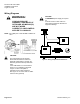
CAUTION:
A SEPARATE power supply is required
if a
4-20 mA sensor is used. Failure to
follow wiring precautions will result in
equipment damage.
Figure 6. Wiring of Optional 4-20 mA Sensor.