Fume Hood Monitor Owner’s Manual 125-1991 Rev.
Rev. 4, June, 2000 NOTICE The information contained within this document is subject to change without notice and should not be construed as a commitment by Siemens Building Technologies, Inc. Siemens Building Technologies, Inc. assumes no responsibility for any errors that may appear in this document. All software described in this document is furnished under a license and may be used or copied only in accordance with the terms of such license.
Table of Contents How to Use This Manual ................................................................................................. III Manual Organization..................................................................................................... III Manual Conventions ..................................................................................................... IV Manual Symbols .........................................................................................................
Fume Hood Monitor Owner’s Manual External alarm and notification................................................................................. 4-3 Point database ......................................................................................................... 4-4 Chapter 5 - Application 650–Slave Mode..................................................................... 5-1 Overview....................................................................................................................
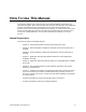
How To Use This Manual This manual is written for the owner and user of the Siemens Building Technologies, Inc. Fume Hood Controller. Direct communication with the Fume Hood Controller is accomplished by using the portable operator's terminal and CIS. For more information about these products, contact your local Siemens Building Technologies, Inc. representative.
Fume Hood Monitor Owner’s Manual Manual Conventions The following table lists conventions to help you use this manual in a quick and efficient manner. Convention Example Numbered Lists (1,2,3…) indicate a procedure with sequential steps. 1. Turn OFF power to the field panel. Turn ON power to the field panel. 2. Contact your local Siemens Building Technologies representative. Type F for Field panels. Actions that you should perform are specified in boldface font.
1 Introduction Chapter 1 describes the Fume Hood Monitor and accessories. The following topics are discussed: • Fume Hood Monitor (FHM) Controller • Communicating with Your FHM • Ordering Information Fume Hood Monitor (FHM) Controller The Fume Hood Monitor (FHM) is a display device, as well as the interface between the current operating condition of the fume hood and the operator.
Fume Hood Monitor Owner's Manual 1-2 Siemens Building Technologies, Inc.
2 External Hardware Components Chapter 2 describes the external Fume Hood Monitor hardware. Chapter 2 discussed the following topics: • Fume Hood Monitor • External Components − LCD Text Strings − LED status − Button functions • Portable Operator’s Terminal port • Airflow sensor input The Fume Hood Monitor The Fume Hood Monitor (FHM) is a Siemens Building Technologies, Inc. Laboratory Control product. The FHM provides visual and audible alarms to alert a fume hood user of airflow conditions.
Fume Hood Monitor Owner's Manual Figure 2-1. FHM External Components. LCD Text Strings The LCD can show the face velocity of the fume hood in ft/min. or m/sec. It also shows the status of the FHM with the following text strings: Text String… … 2-2 Indicates that… … LOW FACE VELOCITY The fume hood airflow is below the limit. HIGH FACE VELOCITY The fume hood airflow is above the limit. USER ALARM The user pressed the EMERGENCY button. GENERAL FAILURE A hardware failure exists.
External Hardware Components LED status The LEDs indicate the following status: LED color… … Indicates that the FHM is… … Green Operating in a normal condition. Red In an alarm condition. Button functions The buttons on the FHM have the following functions: Button EMERGENCY Function Pressing this button indicates an alarm condition by turning: • The green LED OFF. • The red LED ON. • The horn ON. Horn Silence Pressing this button will turn the horn OFF.
Fume Hood Monitor Owner's Manual 2-4 Siemens Building Technologies, Inc.
3 Internal Hardware Components Chapter 3 describes the internal Fume Hood Monitor (FHM) hardware. Chapter 3 discusses the following topics: • Circuit Board • Alarm relay definition and specification • Alarm buzzer definition and specification • FLN trunk definition and specification • Operating and power specifications • Wiring diagram Circuit Board The printed circuit board of the FHM (Figure 3-1) is the central processing area.
Fume Hood Monitor Owner's Manual Figure 3-1. FHM Internal Components. ay Alarm rela The alarm relay is a set of contacts that can be used, with the appropriate wiring, to indicate an alarm condition to a centralized control system. Alarm relay contact status… … Indicates that the fume hood… … Closed is operating in a normal condition. Open is operating in an alarm condition. Specification Alarm relay contacts 3-2 N.C.
Internal Hardware Components Digital input The digital input (DI) is an auxiliary input that can be used for the input of DI Functions or for custom-defined operations. The DI functions are: Sash height alarm, high face velocity alarm disable, DI alarm point of OCC/UNOCC monitor. This is a dry contact input. Specification Recommended wire 20 AWG Twisted Shielded Pair (TSP) Recommended max. wire length 100 ft. (30.5 m) Max.
Fume Hood Monitor Owner's Manual Wiring diagram The following illustration (Figure 3-2) is the wiring diagram for the FHM. Figure 3-2. FHM Wiring Diagram. 3-4 Siemens Building Technologies, Inc.
4 Application 651 – Operating Mode Chapter 4 describes the Application 651 – Operating Mode available in the FHM. The FHM may be stand-alone or connected to a field panel. The FHM can also send an alarm notification to a centralized control system. Table 4-1 contains Operating Mode point database information. Overview Application 651 is one of two FHM applications. This application is the Operating Mode, which determines the features that are available to the user.
Fume Hood Monitor Owner's Manual Alarm actions The FHM contains the following general alarm action sequence: If… … Then… … The FHM displays… … the FHM detects an alarm the green LED turns OFF, the red LED illuminates, ALARM STATUS (Point 7) changes from NORMAL to ALARM, the horn sounds, and the contacts of the alarm relay open. LOW FACE VELOCITY, HIGH FACE VELOCITY, USER ALARM, or “EEE” depending on the type of alarm.
Applications 651–Operating Mode Alarm limits The FHM contains low and high face velocity alarm limits, LO ALM LMT (Point 13) and HI ALM LMT (Point 10). These points apply to LOW ALM (Point 5) and HIGH ALM (Point 6). When the face velocity is… … Then… … The FHM displays… … lower than LO ALM LMT (Point 13) for a time greater than ALARM TIME (Point 96) LOW ALM (Point 5) will toggle to ON.
Fume Hood Monitor Owner's Manual Point database The following table contains all of the points in Application 651. Calibration Report points are numbered in the 80s. Set-up Report points are numbered in the 90s. Table 4-1. Point Database for Fume Hood Monitor Application 651. Point Number Descriptor 1 CTLR ADDRESS 99 2 APPLICATION 651 {4} FACE VEL -- {5} LOW ALM {6} HIGH ALM {7} ALARM STATUS 1. Factory Default (SI units) Engr.
Applications 651–Operating Mode Table 4-1. Point Database for Fume Hood Monitor Application 651. (continued) Point Number Descriptor Factory Default (SI units) Engr. Units (SI units) Slope (SI units) Intercept (SI units) On Text Off Text 71 MAX RAW 150 -- -- -- -- -- 73 MID RAW 100 -- -- -- -- -- 75 MIN RAW 60 -- -- -- -- -- 80 CAL REQUEST NO -- -- -- YES NO 81 MAX FVEL 150 (0.
Fume Hood Monitor Owner's Manual 4-6 Siemens Building Technologies, Inc.
5 Application 650 – Slave Mode Chapter 5 describes the Application 65 – Slave Mode available in the FHM. When the FHM is connected to a field panel, it may be controlled in Slave Mode. Table 5-1 contains Slave Mode point database information. Overview Application 650 is one of two FHM applications. Slave Mode is the state of the FHM when it is shipped from the factory. In Slave Mode, the FHM displays “OFF” and the red and green LEDs are OFF.
Fume Hood Monitor Owner's Manual Point database The following table contains all of the points in Application 650. Table 5-1. Point Database for Fume Hood Monitor Application 650. Point Number Descriptor Factory Default (SI units) Engr.
6 Point Database Chapter 6 presents a description of the Fume Hood Monitor (FHM) point database including point descriptors, point addresses, and a listing of applications in which each point is found. Descriptor Address Application Description CTLR ADDRESS 1 650, 651 Identifies the FHM on the Siemens Building Technologies, Inc. FLN trunk. Valid values: 0 through 31. APPLICATION 2 650, 651 The identification number of the program operating in the FHM. Valid values are 650 and 651.
Fume Hood Monitor Owner's Manual Descriptor Address Application Description LO ALM LMT 13 651 This point sets the value, in fpm (m/s), which is used for the Low Alarm set point (refer to Point 5). OCC UNOCC 29 650, 651 This point indicates the mode of occupied or unoccupied. When mode is UNOCC, the red LED is ON, the green LED is OFF, and the LCD displays OFF.
Point Database Descriptor HORN SILENCE Address Application 61 651 Description Indicates if the first button (labeled “Horn Silence”) has been pressed. If no alarm condition is present, then the state of the point remains at OFF. If an alarm exists, then the horn will silence and the status will change to ON. When the alarm condition clears, the point will reset to OFF. AUX BUTTON 1 62 651 The hardware input, point BUTTON 2 (Point 57), is logically tied to this point.
Fume Hood Monitor Owner's Manual Descriptor Address Application Description MID FVEL 83 651 Represents the field calibration mid face velocity. The mid face velocity is found using the portable velocity probe and moving the sash to a mid calibration velocity position. MID DONE 84 651 The person performing calibration toggles this point to save the entered mid velocity calibration value to EEPROM. MIN FVEL 85 651 Represents the minimum field calibration face velocity.
7 Hardware and Software Troubleshooting Chapter 7 describes corrective measures you can take should you encounter a problem when using a Fume Hood Monitor (FHM) or the Computer Interface Software (CIS). For issues not covered in this chapter, contact your local Siemens Building Technologies, Inc. representative. Fume Hood Monitor Troubleshooting You are not required to do any FHM troubleshooting. Contact your local Siemens Building Technologies, Inc.
Fume Hood Monitor Owner's Manual 7-2 Siemens Building Technologies, Inc.
Glossary Overview Tthe glossary contains terms and acronyms that are used in this manual. For definitions of point database descriptors, refer to Chapter 6 - Point Database in this manual. For definitions of commonly used terms, as well as acronyms and abbreviations associated with APOGEE, refer to the Technical Glossary of Building Controls Terminology and Acronyms (125-2185). This book is available from your local Siemens Building Technologies, Inc. representative. AI Analog Input.
Fume Hood Monitor Owner's Manual DO Digital Output. A physical point that generates a two-state signal (such as, ON/OFF, OPEN/CLOSED, or YES/NO). EEPROM Electronic Erasable Programmable Read Only Memory. Non-volatile memory. English units The foot-pound-second system of units for weights and measurements. face velocity Average air velocity through the face of the fume hood. firmware Category of memory chips that hold their content without electrical power.
Glossary LED Light Emitting Diode. Portable Operator’s Terminal Laptop computer used with the CIS to communicate with FHMs. SI units Systeme International d’Unites. The international metric system. Slave Mode Default application that comes up when power is first applied to a factory new FHM. No control action is initiated in the Slave Mode. Siemens Building Technologies, Inc.
Fume Hood Monitor Owner's Manual Glossary-4 Siemens Building Technologies, Inc.
Index A airflow sensor input .........................................2-3 alarm action sequence ..........................................4-2 buzzer specification .....................................3-3 external notification .....................................4-3 limits high ..........................................................4-3 low............................................................4-3 relay definition ..................................................3-2 specification ...................
Fume Hood Monitor Owner’s Manual power failure, result of FHM............................7-1 power specification .........................................3-3 preventive maintenance..................................7-1 digital input .................................................. 3-3 FLN trunk .................................................... 3-3 operating ..................................................... 3-3 power ..........................................................