
Basic Documentation
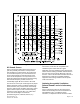
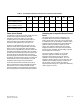

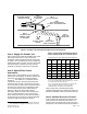
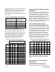

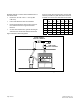
Table Of Contents
- Getting a Handle on Decibels
- The Frequency Component
- The Octave Bands
- Sound Curves
- Now Come the Complications and Confusion
- NC Sound Curves
- Attaining Acceptable Ventilation Related Sound Levels in Laboratory Rooms
- Equipment Sound Ratings
- Fume Hood Sound
- Attaining an Acceptable Room Sound Level
- Example Analysis of a VAV Research Laboratory Room Supply Air System
- Item 1: Supply Air Sound Level
- Item 2: Space Effect Sound Attenuation
- Item 3: Multiple Sources of Sound
- Item 4: Allowable Supply Air Sound at Diffusers
- Item 5: End Reflection Sound Attenuation at Supply Diffuser Inlet
- Item 6: Supply Air Terminal Duct Attenuation
- Item 7: Duct Division
- Item 8: Allowable Supply Terminal Discharge Sound
- Allowable Room Sound Level
- Room General Exhaust Terminal
- VAV Fume Hoods
- Suggestions for Reducing Excess Room Related Ventilation System Sound
- Conclusion

Octave Bands
Room Ventilation - Component Sound Analysis
2 3 4 5 6 7
Item Description
125
Hz
250
Hz
500
Hz
1000
Hz
2000
Hz
4000
Hz
1
Allowable Room Sound
Level
Attenuation
2
Resultant
Attenuation
3
Resultant
Attenuation
4
Resultant
Attenuation
5
Resultant
Attenuation
6
Resultant
Attenuation
7
Resultant
Attenuation
8
Resultant
Attenuation
9
Resultant
Attenuation
10
Resultant
Figure 2. Room Ventilation System - Component Sound Levels Analysis Chart.
Example Analysis of a VAV Research
Laboratory Room Supply Air System
Room Size: 12 ft W × 25 ft L × 9 ft H (2,592
cubic feet)
Two Fume Hoods at 1200 cfm maximum per
fume hood
Supply Air Terminal: 12-inch single duct with
reheat
Supply Airflow: 2000 cfm maximum
Supply Diffusers: Two 48 inch × 24 inch radial
diffusers
Figure 3 shows a diagram of the example room
sup
ply air configuration and Figure 4 records the
entries of the supply air system sound analysis in a
copy of the chart of Figure 2.
Page 6 of 12
Siemens Industry, Inc.
Document No. 1
49-979