
Commissioning Instructions


Before You Begin
Setting External Face Area Input
8 | 10
Siemens Industry, Inc.
A6V10801608
Restricted
07.06.2016
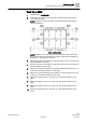
Sash Calibration Verification
1.
Close the vertical sash fully and verify that the value displayed at POS
SASH1 is at the minimum that was set during calibration. Open the sash
half way and verify that the value displayed at POS SASH 1 is equal to the
current measured value. Open the sash fully and verify that the value
displayed at POS SASH 1 is at the maximum that was set during calibration.
See Table
Sash/Point Wiring
.
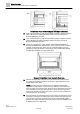
2.
Repeat this verification procedure for the remaining sash panels using the
appropriate corresponding points. See Table
Sash/Point Wiring
.
Sash/Point Wiring
Sash Panel
Point
Descriptor
Vertical 1
31
POS SASH 1
Vertical 2
32
POS SASH 2
Vertical 3
33
POS SASH 3
Vertical 4
34
POS SASH 4
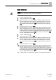
Setting External Face Area Input
Skip this section if you are only using one SOAM, leave values at default.
AI can be set up as an input for external face area.
1. Set MAX EXT AREA to the area corresponding to 10 volts from the input signal
source.
The next step allows the minimum voltage to bet set to a value other than 1
(default). The minimum voltage is represented when the face area is equal
to 0.
2. Set MIN EXTVOLTS to the voltage corresponding to 0 face area from the input
signal source. (default = 1.0 Vdc)
The resulting area displays in point EXTERNAL A.
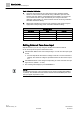
NOTE:
If no external area input is be connected to the AI, make sure MAX EXT AREA =
0 (default). This disables the alarm feature that fails the FACE AREA point when
the input signal drops below 1 Vdc.