
Data Sheet for Product

Page 12 of 19 Siemens Industry, Inc.
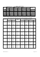
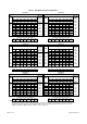
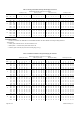
Table 3. Hot Water Reheat Coil Capacities.*
UNIT SIZE 04, 06 UNIT SIZE 04, 06
1-Row Coil 2-Row Coil
GPM
Airflow, CFM
Waterside
GPM
Airflow, CFM
Waterside
Head Head
75 100 200 300 400 500 600 Loss 75 100 200 300 400 500 600 Loss
Heating Capacity (MBH) (ft.wg.) Heating Capacity (MBH) (ft.wg.)
0.50 4.4 5.0 6.8 7.9 8.6 9.2 9.6 0.13 0.60 6.3 7.4 10.5 12.3 13.5 14.4 15.1 0.05
0.75 4.6 5.4 7.4 8.8 9.7 10.5 11.0 0.28 0.75 6.5 7.8 11.2 13.3 14.8 15.9 16.8 0.07
1.00 4.7 5.6 7.8 9.3 10.4 11.2 11.9 0.49 1.00 6.7 8.1 12.0 14.5 16.3 17.7 18.8 0.12
1.50 4.9 5.8 8.3 9.9 11.2 12.2 13.0 1.06 1.50 7.0 8.5 13.0 16.0 18.2 20.0 21.4 0.27
2.00 5.0 5.9 8.5 10.3 11.6 12.7 13.6 1.86 2.00 7.2 8.8 13.6 16.9 19.4 21.4 23.0 0.47
2.50 5.0 6.0 8.7 10.5 11.9 13.1 14.0 2.87 2.50 7.3 8.9 13.9 17.5 20.2 22.4 24.2 0.72
3.00 5.0 6.0 8.8 10.7 12.1 13.3 14.3 4.08 3.00 7.3 9.0 14.2 17.9 20.7 23.1 25.0 1.02
4.00 5.1 6.1 8.9 10.9 12.4 13.7 14.7 7.13 4.00 7.4 9.1 14.5 18.4 21.5 24.0 26.1 1.79
Air Side Pressure Drop (Inches WC) Air Side Pressure Drop (Inches WC)
0.01 0.01 0.04 0.07 0.12 0.18 0.24 0.02 0.03 0.08 0.16 0.26 0.38 0.51
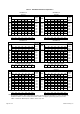
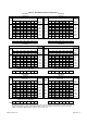
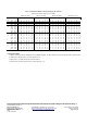
UNIT SIZE 04, 06 UNIT SIZE 04, 06
3- Row Coil 4- Row Coil
GPM
Airflow, CFM
Waterside
GPM
Airflow, CFM
Waterside
Head Head
75 100 200 300 400 500 600 Loss 75 100 200 300 400 500 600 Loss
Heating Capacity (MBH) (ft.wg.) Heating Capacity (MBH) (ft.wg.)
1.00 8.2 10.2 15.7 19.2 21.7 23.6 25.0 0.19 1.5 9.1 11.5 18.9 23.9 27.5 30.3 32.6 0.23
1.50 8.5 10.5 16.8 21.1 24.3 26.8 28.8 0.42 3 9.3 11.9 20.5 26.8 31.8 35.9 39.3 0.88
2.00 8.6 10.7 17.5 22.3 25.9 28.8 31.1 0.72 4 9.4 12.1 20.9 27.7 33.1 37.6 41.4 1.55
2.50 8.6 10.9 17.9 23.0 26.9 30.1 32.7 1.11 5 9.4 12.1 21.2 28.2 34.0 38.7 42.8 2.39
3.00 8.7 11.0 18.2 23.5 27.6 31.0 33.9 1.58 6 9.4 12.2 21.4 28.6 34.5 39.5 43.8 3.41
4.00 8.7 11.1 18.5 24.1 28.6 32.3 35.4 2.74 7 9.5 12.2 21.5 28.9 34.9 40.1 44.5 4.61
5.00 8.8 11.1 18.8 24.6 29.2 33.1 36.4 4.23 8 9.5 12.2 21.6 29.1 35.3 40.5 45.1 5.98
6.00 8.8 11.2 18.9 24.9 29.7 33.7 37.1 6.01 9 9.5 12.2 21.7 29.2 35.5 40.9 45.6 7.53
Air Side Pressure Drop (Inches WC) Air Side Pressure Drop (Inches WC)
0.02 0.04 0.12 0.24 0.39 0.56 0.77 0.03 0.05 0.16 0.32 0.52 0.75 1.02
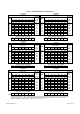
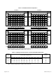
UNIT SIZE 08 UNIT SIZE 08
1-Row Coil 2-Row Coil
GPM
Airflow, CFM
Waterside
GPM
Airflow, CFM
Waterside
Head Head
150 350 500 650 800 950 1100 Loss 150 350 500 650 800 950 1100 Loss
Heating Capacity (MBH) (ft.wg.) Heating Capacity (MBH) (ft.wg.)
0.5 6.9 9.6 10.7 11.5 12.1 12.6 13.0 0.17 0.6 10.2 14.7 16.4 17.7 18.5 19.2 19.8 0.06
1.0 7.8 11.4 13.1 14.4 15.3 16.1 16.8 0.66 1.0 11.4 17.5 20.2 22.1 23.6 24.7 25.7 0.17
1.5 8.1 12.3 14.2 15.7 16.9 17.9 18.7 1.44 2.0 12.5 20.5 24.4 27.3 29.7 31.6 33.2 0.64
2.0 8.3 12.7 14.8 16.5 17.8 18.9 19.8 2.50 3.0 12.9 21.8 26.2 29.7 32.5 34.9 36.9 1.39
2.5 8.4 13.0 15.2 17.0 18.4 19.6 20.6 3.85 4.0 13.2 22.5 27.3 31.1 34.2 36.8 39.1 2.43
3.0 8.5 13.2 15.5 17.3 18.8 20.1 21.2 5.48 5.0 13.3 23.0 28.0 32.0 35.3 38.1 40.5 3.72
4.0 8.6 13.5 15.9 17.8 19.4 20.7 21.9 9.56 6.0 13.4 23.3 28.5 32.6 36.1 39.0 41.6 5.32
4.5 8.7 13.6 16.1 18.0 19.6 21.0 22.2 12.01 7.0 13.5 23.5 28.8 33.1 36.7 39.7 42.4 7.14
Air Side Pressure Drop (Inches WC) Air Side Pressure Drop (Inches WC)
0.01 0.06 0.11 0.17 0.24 0.33 0.42 0.03 0.13 0.23 0.36 0.51 0.68 0.87
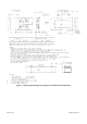
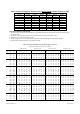
* Notes:
All capacities are based on 180°F entering water temperature and 55°F entering air temperature. For other air and water inlet
temperature conditions, use the correction factors shown in Table 4 to multiply the given heating capacity for each size.
1 MBH = 1000 BTU/Hr. MBH Required = 0.00108 × CFM × Temp. Rise