
Installation Instructions

Installation Instructions
Document No. 546-14401
February 27, 2004
LRC Electronic VAV/CV with HW Reheat and Slow
Actuation Venturi Supply and Exhaust — Analog Output
546-14401, Rev. 010 Page 1 of 7
Product Description
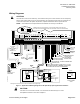
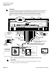
This Laboratory Room Controller (LRC) provides
Direct Digital Control (DDC) of a laboratory room
with one supply duct, one exhaust duct, and up to
four sources of external exhaust. It features VAV or
CV airflow control, slow actuation of venturi air
valves via 0 to 10V AOs, and hot water reheat. It can
operate stand-alone, networked, or with a field
panel. If CE compliance is desired, a ferrite filter and
an alternate room temperature sensor cable must be
used (see Product Numbers).
This LRC can be ordered with or without Air Velocity
Sensor (AVS) transducers mounted on the board. If
ordered without AVS transducers mounted on the
board, two Remote Air Modules (RAM) are required.
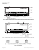
Shipping carton contains a controller assembly
(controller board and cover), a mounting rail, and
two self-tapping screws.
NOTE: Keep the controller in its static-proof bag
until installation.
Product Numbers
Product Description
550-264B
LRC with HW Reheat and Slow Actuation
Venturi Supply and Exhaust—onboard AVS
550-767A
LRC with HW Reheat and Slow Actuation
Venturi Supply and Exhaust—offboard AVS
(requires two Remote Air Modules)
550-818A
Remote Air Module (two required—ordered
and shipped separately)
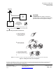
The LRC is designed to work with GDE 161.1P electric
actuators (order separately).
Parts for CE Compliance
588-100A 25 ft (7.6 m)
588-100B 50 ft (15.2 m)
588-100C
2-RJ11 room sensor
cable with alternate
twisted pairing
100 ft (30.48 m)
550-705 clamp-on ferrite filter 10 pack
Installation Conventions
CAUTION
Equipment damage or loss of
data may occur if user does not
follow procedure as specified.
Required Tools
• Electro-Static Discharge (ESD) wrist strap
• Small and medium flat-blade screwdrivers
• Electric drill
• 1/4-inch (6.35 mm) hex nut bit
Additional tools if not using self-tapping option:
• 1/4-inch nut driver
• 1/8-inch (3 mm) bit
Prerequisites
• Wiring conforms to NEC and local codes
and regulations.
• Floor level network (FLN) with 24-volt wiring.
• Supply power to the unit OFF.
• Any necessary hardware installed: terminal
unit, actuator(s), sensor(s), etc.
• Room Temperature Sensor (RTS) installed
(optional). Note: a low-cost temporary RTS
(P/N 540-658P25) is available that plugs into
the RTS port on the LRC, providing
temperature input and actual space control
until a permanent RTS is installed.
Expected Installation Time
New controller installation 10 min.
Replacement with removable
terminal blocks
6 min.
Replacement without removable
terminal blocks
16 min.
NOTE: You may require additional time for
database work at the field panel.