
Installation Instructions

Document No. 546-14401
Installation Instructions
February, 2004
Installation Instructions
NOTE: Follow all safety regulations and local
codes when installing this equipment.
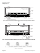
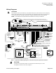
1. Using the mounting rail as a template (Figure 1
or Figure 2), mark the screw holes where you
will install the LRC.
2. Do one of the following:
• If using self-tapping screws, fasten the
mounting rail using a drill and hex nut bit.
• If not using self-tapping screws, drill two 1/8-
inch (3 mm) pilot holes, then fasten the
mounting rail with No. 6 or No. 8 screws.
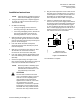
3. With the ESD wrist strap attached to your wrist
and a good earth ground, remove the controller
from the anti-static bag and snap it securely into
place on the mounting rail.
4. If the LRC will be used with a field panel,
disconnect the floor level network (FLN) trunk
from the field panel.
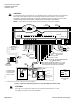
5. Wire the FLN trunk to the LRC (Figure 3). After
all controllers are connected to the FLN,
reconnect the FLN trunk to the field panel.
6. If the LRC requires Remote Air Modules, install
them now following the Installation Instructions
(550-819).
7. Connect the point wiring. See Figure 7 if the
LRC requires Remote Air Modules. See Figure 8
if the LRC has onboard AVS transducers.
NOTE: Each DO provides a Normally Open
(NO) and a Common (C) terminal.
Terminate both connections of a 24
Vac load directly to the board.
CAUTION:
The LRC DOs control 24 Vac loads
only. The maximum rating is 12 VA for
each DO. Use an interposing 220V
relay module for VA requirements
higher than the maximum, 110 or 220
Vac requirements, DC power
requirements, or whenever a separate
transformer is used to power the load.
550-264B uses relay module 550-054.
550-767A uses relay module 540-147.
8. Plug the room temperature sensor cable into the
RTS port on the controller (Figure 1 or Figure 2).
If CE compliance is required, a ferrite filter must
be installed on an approved 588-100 series
room temperature sensor cable. See Figure 10.
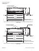
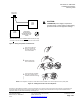
9. Connect a certified 24 Vac Class II power
source to the LRC’s power supply terminal block
by inserting a 1/8-inch flat blade screwdriver into
a rectangular slot on the terminal block (Figure
4). The screwdriver will come into contact with a
lever. Continue applying pressure until the lever
releases and moves out of the way. Insert the
wire and then remove the screwdriver.
LAB0108R1
1 - 1/4
(32)
15/16
(24)
1 - 3/8
(34)
DIMENSIONS IN INCHES
MILLIMETERS IN PARENTHESES
Figure 4. Terminal Block.
The installation is complete.
Siemens Building Technologies, Inc. Page 3 of 7