
Installation Instructions

Document No. 546-14401
Installation Instructions
February, 2004
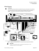
#8 TAPPING SCREW HOLE
11/64 (4) DIA. CLEARANCE
DIMENSIONS IN INCHES
MILLIMETERS IN PARENTHESES
4-1/8
(105)
10-29/32
(277)
3/16
(5)
TEC0462R1
C
L
11-9/32
(287)
1-27/32
(47)
1 2 3 4 5 6 7 8 9 10 11 12 13 14 15 16
1 2 3 4 5 6 7 8 9 10 11 12 13 14 15 16
+-
S
+-
S
+-
S
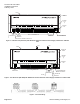
Figure 5. Dimensions for LRC Electronic with HW Reheat and Slow Actuation Venturi Supply and Exhaust.
(Offboard AVS)
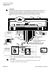
#8 TAPPING SCREW HOLE
11/64 (4) DIA. CLEARANCE
DIMENSIONS IN INCHES
MILLIMETERS IN PARENTHESES
4-1/8
(105)
10-29/32
(277)
3/16
(5)
TEC0461R1
C
L
11-9/32
(287)
1-27/32
(47)
1 2 3 4 5 6 7 8 9 10
+-
S
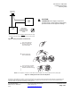
2 (51)
CLEARANCE REQUIRED
FOR PROPER INSERTION
OF POLYETHYLENE TUBING
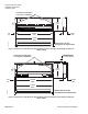
Figure 6. Dimensions for LRC Electronic with HW Reheat and Slow Actuation Venturi Supply and Exhaust.
(Onboard AVS)
Page 4 of 7 Siemens Building Technologies