
Installation Instructions

Document No. 546-14401
Installation Instructions
February, 2004
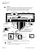
24 VDC
POWER
SUPPLY
4-20 mA
SENSOR
ENTIRE CIRCUIT
MUST BE ISOLATED
WITH NO EARTH GROUND,
INCLUDING THE 4-20 mA
SENSOR
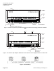
You can NOT use the same transformer to power both the sensor and the controller.
NOTE: Each 4-20mA sensor requires a SEPARATE, dedicated 24 VDC power supply.
-+
-
+
TEC0429R1
ANALOG INPUT
TERMINATIONS
CAUTION:
A SEPARATE power supply is required if a
4-20 mA sensor is used. Failure to follow wiring
precautions will result in equipment damage.
Figure 9. Wiring of Optional 4-20 mA Sensor.
TEC0320R2
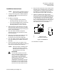
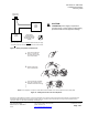
1- 2 cm
1
Open the ferrite filter and
place it 1-2 cm from the
end of the cable or wiring
that is to be shielded.
2
Wind the cable tightly
twice around the filter.
3
Close the filter and wrap tightly
with a zip tie (wrap the zip tie
OVER the wound cable or wiring).
NOTE: If CE compliance is required, a ferrite filter must be installed on the room temperature sensor (RTS) cable.
Figure 10. Adding Ferrite Filter for CE Compliance.
Information in this publication is based on current specifications. The company reserves the right to make changes in specifications and
models as design improvements are introduced. Other product or company names mentioned herein may be the trademarks of their
respective owners. © 2004 Siemens Building Technologies, Inc.
Siemens Building Technologies, Inc.
1000 Deerfield Parkway
Buffalo Grove, IL 60089-4513
U.S.A.
Your feedback is important to us. If you
have comments about this document,
please send them to
technical.editor@sbt.siemens.com
Document No. 546-14401
Printed in the U.S.A.
Page 7 of 7