PRC-OAVS Room Pressurization with Floating Damper Control, AOV or Floating Reheat, Optional Discharge Control and Optional AOV Perimeter Radiation Owner’s Manual 125-5085 125-5085 06/30/2015 Building Technologies
Table of Contents How To Use This Manual .................................................................................................. 4 Chapter 1 – Product Overview ......................................................................................... 6 Hardware Inputs .................................................................................................................. 7 Hardware Outputs ...................................................................................................
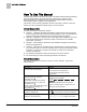
How To Use This Manual How To Use This Manual This manual is written for the owner and user of the PRC-OAVS with Floating Damper, AOV or Floating Reheat, (optional) Discharge Temperature Control and AOV Perimeter Heating. It is designed to help you become familiar with the Siemens Pressurization Room Controller and its applications. This section covers manual organization, manual conventions, symbols used in the manual, and other information that will help you use this manual.
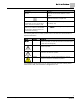
How To Use This Manual Convention Examples New terms appearing for the first time are The field panel continuously executes a useritalicized. defined set of instructions called the control program. This symbol signifies Notes. Notes provide additional information or helpful hints. Cross references to other information are For more information on creating flowcharts, see indicated with an arrow and the page Flowcharts [→92].
Chapter 1 – Product Overview Hardware Inputs Chapter 1 – Product Overview The PRC-OAVS with Floating Damper, AOV or Floating Reheat, (optional) Discharge Temperature Control and AOV Perimeter Heating is the Siemens Industry FLN controller used in pressure independent Variable Air Volume applications. It provides Direct Digital Control (DDC) for a number of applications. The controller can operate as an independent, stand-alone, DDC room controller or it can be networked with a field panel.
Chapter 1 – Product Overview Hardware Inputs Hardware Inputs Analog Air velocity sensor (one or two depending on setup) Application 2963 Room temperature sensor Application 2963 Discharge temperature sensor (10K (default) or 100K Ω software selectable thermistor) Application 2963 (Optional) Room temperature setpoint dial Application 2963 Digital Occupancy button (option on room temperature sensor) Application 2963 (Optional) Occupancy switch Application 2963 (Optional) Pressurization selection
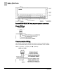
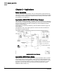
Chapter 1 – Product Overview Power Wiring Generic Controller I/O Layout. See Wiring Diagram for application specific details. Power Wiring Communication Wiring The controller connects to the field panel by means of a Floor Level Network (FLN) trunk. Communication wiring connects to the three screw terminals on the controller labeled “+” (positive), “-“ (negative), and “ ” (reference). 8 Siemens Industry, Inc.
Chapter 1 – Product Overview Temperature Sensors Temperature Sensors Temperature sensors used with the PRC-OAVS with Floating Damper, AOV or Floating Reheat, (optional) Discharge Temperature Control and AOV Perimeter Heating include an electronic room temperature sensor and an optional duct temperature sensor. Room Temperature Sensor The controller room temperature sensor connects to the controller by means of a cable terminated at both ends with a six-conductor RJ-11 plug-in connector.
Chapter 2 – Applications Basic Operation Chapter 2 – Applications Basic Operation The PRC-OAVS with Floating Damper, AOV or Floating Reheat, (optional) Discharge Temperature Control and AOV Perimeter Heating provides Direct Digital Control (DDC) technology for pressure independent Variable Air Volume (VAV) and Constant Volume (CV) laboratory room applications.
Chapter 3 – Point Database Chapter 3 – Point Database Chapter 3 presents a description of the PRC-OAVS with Floating Damper, AOV or Floating Reheat, (optional) Discharge Temperature Control and AOV Perimeter Heating point database, including point descriptors, point addresses, and a listing of applications in which each point is found. Address1 Application CTLR ADDRESS 01 All APPLICATION 02 2965 Identification number of the program running in the controller.
Chapter 3 – Point Database Address1 Application FLOW START 16 2963 Determines how the damper modulation will be sequenced while in heating mode. When HTG LOOPOUT is above this value, then FLOW STPT starts to increase. FLOW END 17 2963 Determines how the damper modulation will be sequenced while in heating mode. When HTG LOOPOUT is below this value, then FLOW STPT starts to decrease.
Chapter 3 – Point Database Address1 Application HTG FLO MIN 33 2963 The minimum amount of air in cfm (lps) to be supplied to the space in heating mode. HTG FLO MAX 34 2963 The maximum amount of air in cfm (lps) to be supplied to the space in heating mode. {35} 2963 Actual amount of air in cfm (lps) currently passing through the air velocity sensor. 36 2963 Calibration factor for airflow. REHEAT CMD {37} 2963, 2965 The value to which the reheat modulation is commanded.
Chapter 3 – Point Database Address1 Application {53}2 2963, 2965 54 2963 {55} 2963, 2965 PRS1DIF STPT 56 2963 The volume differential setpoint used to provide desired pressurization. PRS2DIF STPT 57 2963 The volume differential setpoint used to provide desired pressurization. REHEAT END 58 2963 Determines how the reheat modulation will be sequenced while in heating mode. When HTG LOOPOUT is below this value, then the reheat modulates downward.
Chapter 3 – Point Database Address1 Application AOV1 {74} 2963, 2965 Displays the voltage signal to AO1. AOV2 {75}2 2963, 2965 Displays the voltage signal to AO2. TEMP CTL VOL {76} 2963 The temperature control loop volume. 77 2963 The value of heating command at which the radiation valve is fully closed. CTL TEMP {78} 2963, 2965 CLG LOOPOUT {79} 2963 The cooling temperature control loop output value in percent.
Chapter 3 – Point Database Address1 Application CAL TIMER 96 2963, 2965 SUPDUCT AREA 97 2963 Area, in square feet (square meters), of the duct where the air velocity sensor is located. This value is calculated by the field panel depending on duct shape and size. It is used in calculating all points in units of cfm, CF, lps, and L. LOOP TIME 98 2963 The time, in seconds, between control loop calculations.
Chapter 3 – Point Database Address1 Application FAIL TIME 121 2963 Indicates when the air volume is too far away from setpoint for too long. ALARM ENA 122 2963 An analog point that determines if and what alarm activates ALARM DO7. MTR SETUP 123 2963, 2965 Sets the presence or absence of a motor and its direction of travel. DO DIR.REV 124 2963, 2965 Reverses the output state for selected non-motor digital outputs.
Chapter 4 – Basic Service and Maintenance Basic Service Information Chapter 4 – Basic Service and Maintenance This chapter describes corrective measures you can take should you encounter a problem when using a Pressurization Room Controller. You are not required to do any controller troubleshooting. You may want to contact your local Siemens Industry representative if a problem occurs or you have any questions about the controller.
Glossary Glossary This glossary contains the collected terms and acronyms that are used in Siemens BACnet PTEC and TEC Controllers. For definitions of point database descriptors, see Chapter 3 - Point Database, in this manual. airflow Rate at which a volume of air moves through a duct. Usually expressed in cubic feet per minute (cfm) or liters per second (lps). algorithm Mathematical formula and control logic that uses varying inputs to calculate an output value. AVS Air Velocity Sensor.
Glossary Demand Control Ventilation A control algorithm that provides for the control or reduction of outdoor air intake below design rates when the actual occupancy of spaces served by the system is at less than design occupancy. DCV Demand Control Ventilation. DDC Direct Digital Control. Direct digital control The automated control of a condition or process by a digital device (computer). DO Digital Output. Physical output point that sends a two-state signal (ON/OFF, OPEN/CLOSED, YES/NO).
Glossary HMI Human Machine Interface. Terminal and its interface program that allows you to communicate with a field panel or equipment controller. Occupancy sensor A control device that detects presence of people in a space by using infrared or ultrasonic technology. Occupancy sensors are used to save energy by controlling lighting and temperature and, along with CO2 sensors, to provide control input of demand control ventilation (DCV) algorithms.
Glossary UI Universal Input. Can be used as an AI or DI. An AI input is a point receiving a signal that represents a condition that has more than two states. A DI input is a physical input point that receives a two-state signal. unbundle Term used to describe the entering of a point that resides in a controller's database into the field panel's database so that it can be monitored and controlled from the field panel. VAV Variable air volume.
Index Index A L actuators, 9 damper actuator, 9 valve actuator, 9 algorithm, 19 application, slave mode overview, 10 loopout, 20 B P basic operation, 10 basic service information, 18 PID, 21 point database overview, 11 preventive maintenance, 18 C centralized control, 19 Chilled Beam, 19 CO2, 19 control loop, 19 controller Terminal Box (VAV) Controller, 6 Terminal Equipment Controller, 6 CV, 19 D DCV, 20 DDC, 20 Demand Control Ventilation, 20 Direct digital control, 20 Direct Digital Control (DDC)
Issued by Siemens Industry, Inc. Building Technologies Division 1000 Deerfield Pkwy Buffalo Grove IL 60089 Tel. +1 847-215-1000 Document ID 125-5085 Edition 06/30/2015 © Siemens Industry, Inc., 2015 Technical specifications and availability subject to change without notice.