
Operating Instructions

Chapter 3 – Point Database
12
Siemens Industry, Inc.
Owner's Manual
125-5085
06/30/2015
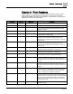
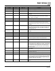
Descriptor
Address
1
Application
Description
FLOW START
16
2963
Determines how the damper modulation will be sequenced
while in heating mode. When HTG LOOPOUT is above this
value, then FLOW STPT starts to increase.
FLOW END
17
2963
Determines how the damper modulation will be sequenced
while in heating mode. When HTG LOOPOUT is below this
value, then FLOW STPT starts to decrease.
WALL SWITCH
18
2963, 2965
YES indicates that the controller is to monitor the status of a
wall switch that is connected to UI 2. NO indicates that the
controller will not monitor the status of a wall switch, even if one
is connected. Valid input: YES or NO.
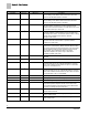
DI OVRD SW
{19}
2
2963, 2965
Actual indication of the status of the override switch (not
physically available on all temperature sensor models) at the
room temperature sensor. ON indicates that the switch is being
pressed. OFF indicates that the switch is released.
Valid input: ON or OFF.
OVRD TIME
20
2963
The amount of time, in hours, that the controller will operate in
day mode when the override switch is pressed while the
controller is in night mode.
NGT OVRD
{21}
2963
Indicates the mode that the controller is operating in with
respect to the override switch. NIGHT indicates that the switch
has not been pressed and the override timer is not active. DAY
indicates that the switch has been pressed and the override
timer is active. The controller then uses a day mode
temperature setpoint. This point is only in effect when
DAY.NGT indicates night mode.
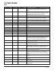
VOL DIF ALM
{22}
2963
Alarm point. ON means room pressurization may not be
adequate.
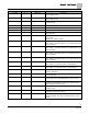
NET ALM CMD
{23}
2963, 2965
The alarm data sent in to PRC from the network.
DI 2
{24}
2963, 2965
Actual status of a contact connected to the controller at DI 2
(screw terminals 15 and 16). ON indicates that the contact is
closed; OFF indicates that the contact is open. If a wall switch
is used, it is connected to DI 2.
DI 4
{25}
2
2963, 2965
Actual status of a contact connected to the controller at DI 3/AI
3 (screw terminals 13 and 14). ON indicates that the contact is
closed; OFF indicates that the contact is open. When a contact
is connected at DI 3, AI 3 is not available.
GEX P GAIN
26
2963
Feedback gain. Used to tune general exhaust flow control loop.
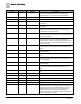
CLG I GAIN
27
2963
The integral gain value for the cooling temperature control loop.
STAT SUPV
{28}
2963, 2965
Room unit configuration point, values are additive.
DAY.NGT
{29}
2963, 2965
Indicates the mode in which the controller is operating.
Occupied temperature setpoints will be used in DAY mode.
Unoccupied temperature setpoints will be used in NGT mode.
This point is normally set by the field panel.
GEX VOL
{30}
2963, 2965
Measured value of the airflow from the room through the
general exhaust terminal.
CLG FLO MIN
31
2963
The minimum amount of air in cfm (lps) to be supplied to the
space in cooling mode.
CLG FLO MAX
32
2963
The maximum amount of air in cfm (lps) to be supplied to the
space cooling mode.