
Operating Instructions

Chapter 3 – Point Database
16
Siemens Industry, Inc.
Owner's Manual
125-5085
06/30/2015
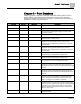
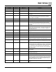
Descriptor
Address
1
Application
Description
CAL TIMER
96
2963, 2965
Time interval, in hours, between the calibration sequence
initiations if a timed calibration option is selected in CAL
SETUP.
SUPDUCT AREA
97
2963
Area, in square feet (square meters), of the duct where the air
velocity sensor is located. This value is calculated by the field
panel depending on duct shape and size. It is used in
calculating all points in units of cfm, CF, lps, and L.
LOOP TIME
98
2963
The time, in seconds, between control loop calculations.
ERROR STATUS
{99}
2963, 2965
The status code indicating any errors detected during controller
power up. A status of 0 indicates there are no problems.
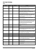
MTR3 TIMING
101
2963, 2965
The status code indicating any errors detected during controller
power up. A status of 0 indicates there are no problems.
MTR3 ROT ANG
102
2963, 2965
The value in units of parts-per-million (PPM).
SWITCH TIME
103
2963, 2965
Room unit configuration point, values are additive.
CAL MODULE
104
2963, 2965
Room humidity when room unit is provided with humidity
sensing.
AOV1 OPEN
105
2963, 2965
The voltage signal to AO1 = OPEN.
AOV1 CLOSE
106
2963, 2965
The voltage signal to AO1 = CLOSED.
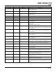
AOV2 OPEN
107
2963, 2965
The voltage signal to AO2 = OPEN.
AOV2 CLOSE
108
2963, 2965
The voltage signal to AO2 = CLOSED.
MTR1 ROT ANG
109
2963, 2965
The angle that Motor 1 rotates from fully closed to fully open.
MTR2 ROT ANG
110
2963, 2965
The angle that Motor 2 rotates from fully closed to fully open.
SWITCH LIMIT
111
2963
The active temperature control loop output must be less than
this value to switch between cooling mode and heating mode.
Actual switchover depends on SWITCH DBAND being
exceeded and is subject to SWITCH TIME being expired.
MTR1 TIMING
112
2963, 2965
The time required for the Motor 1 actuator to travel from full
closed to the full open position.
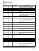
MTR2 TIMING
113
2963, 2965
The time required for the Motor 2 actuator to travel from full
closed to the full open position.
FAIL LIMIT
114
2963, 2965
The error threshold of the Supply or Exhaust (depending on
TRACK MODE) above which the FLOW MODE switches from
STPT to FLOW after the time in FAIL TIME has expired.
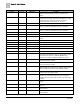
MOD HTG FLO
115
2963
The minimum flow in feet per minute needed for safety
purposes when using electric reheat.
RM CO2
{116}
2963, 2965
A point can be unbundled in the controller for monitoring
purposes. This point may be used in a control strategy as
occupancy increases (CO2 levels increase) in the room being
controlled.
RM RH
{117}
2963, 2965
Room humidity when room unit is provided with humidity
sensing.
DIF ALM DEL
118
2963
Alarm delay point to prevent “nuisance alarms” on the flow
difference.
P1 V ALM LVL
119
2963
Low Ventilation alarm level (CFM/LPS) for TOTL SUPPLY in
Pressure state 1.
P2 V ALM LVL
120
2963
Low Ventilation alarm level (CFM/LPS) for TOTL SUPPLY in
Pressure state 2.