Laboratory Control and Safety Solutions Application Guide s
Laboratory Control and Safety Solutions Application Guide 125-1920 Rev.
Rev.5, January, 2009 NOTICE The information contained within this document is subject to change without notice and should not be construed as a commitment by Siemens Building Technologies, Inc. Siemens Building Technologies, Inc. assumes no responsibility for any errors that may appear in this document. All software described in this document is furnished under a license and may be used or copied only in accordance with the terms of such license.
Table of Contents About this Application Guide ........................................................................................................ I Purpose of this Guide .................................................................................................................. I How this Guide is Organized ....................................................................................................... I Suggested Reference Materials .......................................................
Purpose of this Guide Chapter 4–Ventilation Systems Classification.......................................................................... 13 Types of Ventilation Systems ................................................................................................... 13 CAV Systems ......................................................................................................................... 13 Two-position CAV..................................................................................
Purpose of this Guide Radioisotope Fume Hoods..................................................................................................... 39 Chapter 6–Laboratory Containment Units - Ventilation........................................................... 41 Containment Units .................................................................................................................... 41 Containment Units and Ventilation...........................................................................
Purpose of this Guide Chapter 10–Laboratory Ventilation System - Validation.......................................................... 87 Integrated Laboratory Facility Monitoring and Control ............................................................. 87 Facility Control and Monitoring Functions ................................................................................ 88 Alarm Reports ...................................................................................................................
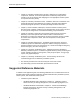
About this Application Guide This section discusses the following topics: • Purpose of this guide. • How this guide is organized. • Conventions and symbols used It also provides information on how to access help and where to direct comments about this guide. Purpose of this Guide This guide provides information to assist in properly configuring laboratory ventilation and the associated control systems.
About this Application Guide • Chapter 5, Laboratory Facility Exhaust Systems, addresses the configurations, components, materials, and control requirements of laboratory facility exhaust systems as an aid to selecting and designing the most appropriate exhaust system for a specific laboratory facility.
Suggested Reference Materials • • − ASHRAE Handbook Fundamentals, Chapter 32 - Duct Design, American Society of Heating, Refrigeration, & Air Conditioning Engineers, Inc.
About this Application Guide Symbols The following table lists the symbols used in this guide to draw your attention to important information. Notation Symbol Meaning WARNING: Indicates that personal injury or loss of life may occur to the user if a procedure is not performed as specified. CAUTION: Indicates that equipment damage, or loss of data may occur if the user does not follow a procedure as specified.
Chapter 1–Introduction Chapter 1 introduces laboratory control and safety solutions. It includes the following topics: • Laboratory control and safety solutions • Intended Audience Laboratory Control and Safety Solutions Proper laboratory room ventilation is an absolute requirement for maintaining the health, safety and well being of laboratory facility occupants.
Chapter 2–Goals of the Laboratory Environment Chapter 2 discusses the goals of the laboratory environment. It includes the following topics: • Occupant health and safety • Room ventilation rates • Ventilation air • Air changes per hour • Occupant comfort versus occupant safety • Room sound level • Emergency provisions Occupant Health and Safety The primary goal of a laboratory ventilation system is to maintain occupant health and safety.
Chapter 2–Goals of the Laboratory Environment Room Ventilation Rates Standards, codes, and various regulatory agencies have established minimum requirements for most laboratory ventilation functions. The first one that we’ll discuss is the minimum room ventilation rate that must be provided to attain an acceptable overall laboratory room environment.
Air Changes Per Hour Recirculated air is also known as return air. During much of the year the required fresh (outside) air must be substantially heated or cooled. However, the temperature and humidity of the return air is much closer to the required room supply air conditions. Thus the use of return air reduces the amount of energy required to provide the temperature and humidity level of the supply air necessary to maintain the required room temperature and humidity.
Chapter 2–Goals of the Laboratory Environment In the same way, one air change per hour will not remove all of the airborne contaminants in a room but will produce a dilution effect. As the rate of air changes per hour is increased, we’ll reduce the concentration of hazardous airborne substances faster; but the time to remove every last trace of such substances could be quite long and just like in the tank example cannot really be determined.
Occupant Comfort Versus Occupant Safety TYPE OF ROOM Hospita l Patient Room Protective Isolation Rooms Infectious Isolation Rooms Biochemistry Lab Animal Lab Autopsy Lab Chemical Storage Room ACH RATE 4 15 6 6 to 10 10 to 15 12 6 OUTSIDE AIR TO ACH RATE 1/3 1/3 1/3 1/3 100% 1/6 1/3 Process Ambient Requirements An experiment or process may require specific room ambient conditions that must be maintained.
Chapter 2–Goals of the Laboratory Environment Research by ASHRAE has established the range of ambient conditions over which the largest percentage of persons feel comfortable when involved in the type of activity generally associated with laboratory work. These conditions range from 71.6°F throughout the winter months to 72.7°F during the summer months. Relative humidity should be maintained within the limits of 30% (winter minimum) to 70% (summer maximum).
Chapter 3–Unique Ventilation Needs of a Laboratory Facility Chapter 3 summarizes the types of individual laboratory rooms likely to be present in a large laboratory facility and their unique ventilation requirements. This is not a complete listing of all possible types of laboratory rooms or of every possible condition that may be encountered. Rather it is intended to enable you to attain an awareness of requirements that will be imposed on the ventilation system for such types of rooms.
Chapter 3–Unique Ventilation Needs of a Laboratory Facility Biosafety Level 2 This classification usually applies to the largest number of microbiological/biomedical laboratories. Although some of the substances present may be infectious, they may be worked on open benches provided that the potential for aerosol release is very low.
High Toxicity Laboratory Rooms High Toxicity Laboratory Rooms This type of laboratory is so designated because of the higher level of hazard posed by the substances and chemicals often used. Federal (U.S. OSHA) and state regulatory agencies have established a list of what substances and chemicals pose, or are suspected of posing, a high risk due to their potential for causing cancer (carcinogens), birth defects, or other potentially very serious adverse affects if exposed.
Chapter 3–Unique Ventilation Needs of a Laboratory Facility Stringent ambient controls appropriate for the species of animals present are necessary to ensure maintaining accreditation and thus validation of the research. Certain room arrangements may also require supplying highly purified air directly to cage racks or having a dedicated HEPA filtered exhaust.
Chapter 4–Ventilation Systems Classification Chapter 4 discusses the various classes of ventilation systems. It includes the following topics: • Types of ventilation systems • VAV systems • Choice of ventilation system Types of Ventilation Systems Ventilation systems for virtually any application can be classified into two general categories: constant air volume (CAV) or variable air volume (VAV).
Chapter 4–Ventilation Systems Classification As the air passes through the laboratory room it provides the required room ventilation (ACH) rate. In cases where the room has chemical fume hoods, biological safety cabinets that are exhausted outdoors, or other types of exhaust needs, the supply air also provides the makeup air for the amount exhausted from these containment units.
Types of Ventilation Systems Two-position CAV A two-position CAV type of ventilation system is essentially the same as the one position CAV system shown in Figure 1. The difference is that the two-position system has a means to provide two separate levels of ventilation airflow. As was indicated previously, standards and codes typically allow a lesser ventilation rate when a laboratory is unoccupied as opposed to when the laboratory is occupied and in use.
Chapter 4–Ventilation Systems Classification The outstanding advantage of a VAV system is that it makes possible a reduction in energy usage during occupied as well as during unoccupied periods. (More specific details on ventilation system energy usage will be provided later in this guide.) Figure 2 illustrates a typical variable air volume ventilation system applied to a laboratory facility.
Choice of Ventilation System In a facility with a VAV type of ventilation system, individual laboratory room air needs will vary mainly in accordance with the extent that VAV fume hood sashes are open. If fume hood users open their sashes only when they actually need access to the inside of their hoods and only as much as necessary, the amount of air that needs to be supplied to the laboratory rooms will be minimized.
Chapter 4–Ventilation Systems Classification The full benefit of a VAV system is most apt to be realized in larger research facilities where there is a multitude of fume hoods, laboratories, and perhaps extensive usage periods in individual laboratory operations. Such situations enable a VAV system to achieve its savings during the longer occupied periods and the incorporation of a VAV diversity factor in the overall HVAC system design.
Chapter 5–Laboratory Facility Exhaust Systems Chapter 5 addresses the applicable configurations, components, materials, and control requirements of laboratory facility exhaust systems as an aid to selecting and designing the most appropriate exhaust system for a specific laboratory facility.
Chapter 5–Laboratory Facility Exhaust Systems Exhaust Systems Overview Regardless of configuration, all facility exhaust systems must meet these requirements: 1. The system capacity and air velocity must reliably collect and transport all hazardous airborne substances (for example, fumes, flammable vapors, airborne pathogens, airborne radioactive particulate, etc.) and the discharge air stream must not pose a hazard to the facility itself or other properties in the area.
Laboratory Exhaust Air ROOF Figure 3. Individual Exhaust System Arrangement Illustrating Separate Exhaust Fans and Exhaust Stacks. Choosing the most applicable arrangement for a facility includes many considerations. The first is typically cost which must include the initial cost and ongoing costs. Ongoing costs primarily include electrical power and maintenance. Aside from cost, other considerations include space requirements, expansion considerations, reliability and redundancy.
Chapter 5–Laboratory Facility Exhaust Systems In larger research facilities with many laboratories and considerable numbers of containment units in close proximity to each other, individual exhaust systems are not the best solution. The accumulation of individual ductwork, fans, and stacks, along with the incremental costs, make individual exhaust systems more costly initially.
Exhaust System Expansion Although various configurations of centralized exhaust systems are possible, it is advisable to always incorporate at least two exhaust fans in each system to enhance the safety and reliability. This ensures that failure of one fan does not result in a total exhaust system failure. Additionally, it is preferable for at least two exhaust fans to be running at all times as the normal operational mode of the exhaust system.
Chapter 5–Laboratory Facility Exhaust Systems Exhaust System Energy Recovery Studies and analysis that have been done on adding energy reclaim systems such as run-around coils or other direct heat transfer methods seldom indicate a payback period that would make such systems economically viable. In contrast, adding additional equipment or mechanisms to the exhaust system usually will result in higher maintenance costs and add additional system reliability concerns.
Proper Exhaust System Functionality Proper Exhaust System Functionality Fume hoods, biosafety cabinets, and other specialty exhaust provisions (snorkels, canopy hoods, etc.) within a laboratory room rely on the adequacy of the exhaust system to achieve their functionality. Without a properly functioning exhaust system these devices can do little to protect the user.
Chapter 5–Laboratory Facility Exhaust Systems AIRFLOW PROOF SWITCH CONTROLLER MOTOR STARTER OUTSIDE AIR BYPASS DAMPER ISOLATION DAMPER ROOF EXHAUST PLENUM STATIC PRESSURE SENSOR LABORATORY EXHAUST Figure 5. Central Exhaust System Static Pressure Control Arrangement with Multiple Constant Volume Fans Discharging into a Single Exhaust Stack.
Centralized Exhaust Systems with Constant Volume Fans Centralized Exhaust Systems with Constant Volume Fans Centralized exhaust systems for either constant air volume or variable air volume ventilation systems are suitable for modest sized facilities. These types of exhaust systems are configured using exhaust fans that run at a constant speed along with a control arrangement that maintains a nearly constant volume of exhaust air through the fans and exhaust stack.
Chapter 5–Laboratory Facility Exhaust Systems The control arrangement of Figure 5 includes other control devices and provisions that are necessary to ensure proper and reliable operation for the overall exhaust system. Each exhaust fan has an airflow proof switch to provide positive feedback of the fan’s operation for system monitoring purposes and to enable automatic activation of a standby fan (not shown in the diagram) in case of an operating fan failure.
Centralized Exhaust Systems with Constant Volume Fans General System Applicability Centralized exhaust systems, similar to Figure 5, that discharge into a single vertical exhaust stack are applicable to smaller and medium sized laboratory facilities. The system must be designed so it is capable of maintaining the desired negative static pressure level within the exhaust system at the maximum required exhaust airflow.
Chapter 5–Laboratory Facility Exhaust Systems Figure 6 shows a large centralized variable air volume exhaust system utilizing individual VAV exhaust fans with individual stacks for each fan. The fans shown are conventional centrifugal type that discharge through a vertical stack. As an option, the fans may be comprised of special laboratory axial exhaust fans designed to entrain large amounts of outside air and discharge the combination upwards at a high velocity thus eliminating the need for a tall stack.
Centralized Exhaust Systems with Constant Volume Fans Variable air volume centralized exhaust systems are typically the best solution for laboratory facilities that have perhaps 30 or more chemical fume hoods. Because the turndown range (ratio of maximum to minimum) exhaust airflow in such facilities may be substantial (4 to 1 ratios being common), the fan speed as well as the exhaust plenum bypass damper are both controlled to maintain the desired negative static pressure level.
Chapter 5–Laboratory Facility Exhaust Systems Exhaust System Discharge Laboratory exhaust must be discharged sufficiently high above the roof so that the exhaust will not re-enter the facility through fresh air intakes or be a problem to nearby structures or property. The common way to attain sufficient discharge height is to utilize a sufficiently high exhaust stack with an adequate exit velocity.
Exhaust System Discharge Stack Diameters and Exit Velocity When conventional stacks are used, the airflow within the stack should be limited to about 2,400 feet per minute (fpm) in order to allow internal condensation to flow downward to a roof drain provided at the base of the stacks. Internal air velocities much higher than this will likely carry condensation droplets out of the stack where their discharge will be subject to the wind speed and direction.
Chapter 5–Laboratory Facility Exhaust Systems Volumetric Airflow cfm 34 Internal Diameter Corresponding To Velocity l/s 2400 fpm (12.19 m/s) 3000 fpm (15.24 m/s) 2,000 944 12.4” 314mm 11.1” 281mm 2,500 1,180 13.8” 351mm 12.4” 314mm 3,000 1,416 15.1” 385mm 13.5” 344mm 3,500 1,652 16.4” 415mm 14.6” 371mm 4,000 1,888 17.5” 444mm 15.6” 397mm 4,500 2,124 18.5” 471mm 16.6” 421mm 5,000 2,360 19.5” 496mm 17.5” 444mm 6,000 2,832 21.4” 544mm 19.
Exhaust System Discharge Volumetric Airflow cfm 100,000 Internal Diameter Corresponding To Velocity l/s 47,192 Siemens Building Technologies, Inc. 2400 fpm (12.19 m/s) 87.4” 2220mm 3000 fpm (15.24 m/s) 78.
Chapter 5–Laboratory Facility Exhaust Systems Laboratory Exhaust Systems - General Requirements Exhaust System Materials Individual exhaust systems for chemical fume hoods pose the harshest environment for exhaust system materials since the fumes from any one fume hood can be very corrosive and highly concentrated. On the other hand, centralized exhaust systems typically benefit from a much higher dilution factor and are therefore less likely to be so severely attacked.
Laboratory Exhaust Systems - General Requirements FRP (Fiberglass Reinforced Polyester) This is a very good all around duct material due to its resistance to most chemicals and its ability to withstand vibration. Epoxy and Teflon® Coated Materials Although these materials have excellent chemical resistivity, it is very difficult to apply them in a manner which forms a very thorough covering without any breaks or seams.
Chapter 5–Laboratory Facility Exhaust Systems Fire Dampers Though normally required where ducts pass through fire rated construction (fire walls), NFPA 45 states that laboratory exhaust systems shall not be equipped with fire dampers. The intent is to ensure against stoppage of the exhaust airflow even if a fire is present. This is in agreement with more advanced fire protection engineering and smoke control technology.
Specialty exhaust systems Radioisotope Fume Hoods Fume hoods used with volatile radioactive materials also require an individual type of exhaust system utilizing 18 gauge, welded, Type 316 stainless steel. However, the overall physical arrangement of the exhaust system need not be different than any other individual exhaust system used for a general purpose fume hood.
Chapter 6–Laboratory Containment Units - Ventilation Chapter 6 discusses containment units specifically intended to allow laboratory occupants to work with and manipulate chemicals, biological specimens, and other potentially hazardous elements.
Chapter 6–Laboratory Containment Units - Ventilation Thus, a proper facility ventilation system design is a fundamental requirement for attaining the protective functionality of a containment unit. This section provides information on how the various types of containment units must interact with the facility ventilation system to achieve maximum protection of the laboratory worker.
Containment Units Class and Type of Biosafety Cabinet: Minimum average face velocity of air entering front opening of cabinet: Contaminatio n protection cabinet provides for biological substances: Method of protecting biological substances Class I Class II Type B3 Class II Type B1 Class II Type B2 75 fpm 75 fpm 100 fpm 100 fpm 100 fpm (0.38 m/s) (0.38 m/s) (0.51 m/s) (0.51 m/s) (0.
Chapter 6–Laboratory Containment Units - Ventilation Table 3. Comparison of Biosafety Cabinet Characteristics (Continued). Class and Type of Biosafety Cabinet: Cabinet exhaust arrangement: Class I HEPA filtered cabinet exhaust air may be returned to room or discharged outdoors via a hard duct connection. Class II Type A Yes (Class I cabinets are not typically arranged to re-circulate exhaust air into a room.
Containment Units Chemical Fume Hoods A chemical fume hood is a ventilated enclosed workspace designed to protect the user against exposure to fumes, vapors and gasses by maintaining a directional airflow into the fume hood through the fume hood’s face opening. Chemical fume hoods are used to protect laboratory workers when conducting a test procedure or doing experimentation involving chemicals or gasses. The air entering the fume hood along with the entrained contaminants is subsequently exhausted out.
Chapter 6–Laboratory Containment Units - Ventilation A laboratory ventilation system designer must know the size, type and the ventilation characteristics of the fume hoods that will be in each individual laboratory room, since they will have a major impact on the required functionality and capacity of the laboratory ventilation system.
Containment Units Average face velocities appreciably exceeding 100 fpm have been found to create turbulence and a “rolling effect” within the fume hood interior and sometimes right at the sash opening. This can result in fumes being carried out through portions of the face opening of the fume hood. Similarly an average face velocity significantly below 100 fpm does not normally provide very effective containment.
Chapter 6–Laboratory Containment Units - Ventilation Since an active airflow control arrangement is not often applied to this type of fume hood, the interaction between the sash and the bypass area is the only means of keeping the face velocity from increasing or decreasing as the sash is repositioned.
Containment Units EXHAUST AIR @ MAXIMUM CFM EXHAUST AIR @ APPROX. 97% EXHAUST AIR @ APPROX. 95% BYPASS AREA MOVABLE SASH 100% OPEN SASH 50% OPEN SASH CLOSED SASH Figure 7. Constant Air Volume Bypass Fume Hood Showing How the Bypass Area Attains a Nearly Constant Exhaust Airflow Regardless of Sash Position. • HOPEC constant volume fume hoods–An energy limiting approach that has applied to constant volume fume hoods is termed the HOPEC fume hood.
Chapter 6–Laboratory Containment Units - Ventilation When applying a HOPEC type of fume hood, the ventilation system’s exhaust provision is configured for about 50% less exhaust airflow from a HOPEC fume hood than from a constant volume bypass fume hood of the same size. Of course, this results in about a 50% reduction in the room makeup air required which yields a saving in the energy required to condition and move the air.
Containment Units With reference to the arrangement of Figure 9, the fume hood controller continuously monitors the movable sash position by means of sash position sensors. This enables the controller to calculate the sash open area (face opening) of the fume hood. For a single vertical opening sash, the vertical sash travel is simply multiplied by the fixed width of the sash opening to obtain the open face area in square feet.
Chapter 6–Laboratory Containment Units - Ventilation Note that the primary purpose of this fume hood control arrangement is to maintain an average face velocity in accordance with current safety standards and regulatory requirements. 10 Precise average face velocity control is attained by the control arrangement of Figure 9, since it mathematically determines the required total exhaust airflow rate necessary to yield the desired average face velocity for any size of fume hood face opening.
Containment Units EXHAUST VAV FUME HOOD CONTROLLER DAMPER EXHAUST AIRFLOW SENSOR OPERATOR DISPLAY PANEL 100 SASH POSITION SENSOR ROOM AIR Figure 9. VAV Fume Hood Face Velocity Control Arrangement. A two-position constant volume bypass fume hood requires a control element in the fume hood exhaust to reduce the exhaust during the unoccupied period.
Chapter 6–Laboratory Containment Units - Ventilation Fume Hood Monitoring Safety standards (that is, ANSI/AIHA Z9.5, NFPA 45, etc.) and regulatory agencies (U.S. OSHA) require all fume hoods to have a monitoring device to inform the fume hood user as to whether the fume hood is providing safe and proper containment. Manufacturers of fume hood control products offer fume hood monitoring devices for this purpose along with various features.
Chapter 7–Room Ventilation, Makeup Air, and Pressurization Control Systems Chapter 7 discusses room ventilation, makeup air, and pressurization control systems in terms of room system configuration, environmental modeling, and pressurization.
Chapter 7–Room Ventilation, Makeup Air, and Pressurization Control Systems Laboratory room exhaust provisions can become quite extensive, thus they should be a focal point for the room ventilation system design. Adequate room exhaust provisions must be provided to ensure removal of contaminated air from the various containment units (that is, chemical fume hoods, biological safety cabinets, etc.) as well as serve the other specialized exhaust needs.
Laboratory Ventilation - Room System Configuration Therefore, a laboratory room ventilation and system must be designed to meet the following criteria: • Provide adequate exhaust for all containment units (fume hoods, biosafety cabinets, etc.), as well as for all other specialized exhaust needs. • Ensure adequate total room exhaust to meet the desired overall room ventilation (air change per hour rate) and maintain the required room ambient conditions.
Chapter 7–Room Ventilation, Makeup Air, and Pressurization Control Systems A D JA C E N T LABO RATO RY ROOM FUM E HO O D SECO NDARY E N T R Y / E X IT C H E M IC A L S TO R A G E L A B O R A TO R Y ROOM G A S C Y L IN D E R S FUM E HO O D S E R V IC E C O R R ID O R PERSONNEL C O R R ID O R P R IM A R Y E N T R Y / E X IT C H E M IC A L S TO R A G E A D JA C E N T LABO RATO RY ROOM Figure 10. Proper Laboratory Room Arrangement.
Laboratory Ventilation - Room System Configuration SUPPLY AIR DIFFUSERS E X H A U S T PRIMARY ENTRY / EXIT FUME HOOD CHEMICAL STORAGE ROOM GENERAL EXHAUST S U P P L Y ROOM AIRFLOW CHEMICAL FUME HOOD STORAGE SUPPLY AIR TERMINAL Figure 11. Proper Laboratory Room Ventilation Arrangement.
Chapter 7–Room Ventilation, Makeup Air, and Pressurization Control Systems The fume hoods or biosafety cabinets may not effectively remove all fumes, vapors and gasses that may be released into the laboratory room itself. A room general exhaust located right above where the area where fume release might occur (near the chemical storage cabinets, gas cylinders, etc.).
Room Environmental Modeling The resulting depiction can be used to verify the suitability of a given ventilation system layout, particularly the suitability of the quantity, type and location of the supply diffusers. This technique is particularly applicable for analyzing a room’s ventilation system with regard to occupant safety.
Chapter 7–Room Ventilation, Makeup Air, and Pressurization Control Systems Laboratory Room Pressurization In addition to providing the minimum required air changes per hour (ACH) for each laboratory room, a properly designed laboratory ventilation system will maintain the laboratories (as well as any rooms having potentially hazardous or pungent fumes) at a negative static pressure with respect to the non-laboratory areas of the facility.
Laboratory Room Pressurization Common pressure measurements are mostly rather high pressures such as steam, compressed air, etc. We don’t need to include the term positive or negative because it is usually obvious to us where the higher pressure is. So, in most everyday references to pressure measurement, we tend to focus only on the numerical value of the higher pressure and we do not need to think in terms of one side being the positive part of a differential pressure measurement.
Chapter 7–Room Ventilation, Makeup Air, and Pressurization Control Systems It is useful to keep the following points in mind with reference to room pressurization: • Room static pressure is the result of the force imposed on the room air mainly from the HVAC system fans. • Room static pressure can only be measured as the difference in static pressure with respect to another location. This is typically another room or an adjacent corridor, but it can also be the outside of the building.
Laboratory Room Pressurization Advantages and Disadvantages of Room Pressurization Control by Pressure Sensing Room static pressure control by pressure sensing enables precise closed loop control of the desired room static pressure in applications where the room ventilation airflow is constant (constant volume laboratories). It is also generally an appropriate way to handle situations where multiple levels of pressurization might be desirable between several rooms (+0.02 in. WC in one room, +0.01 in.
Chapter 7–Room Ventilation, Makeup Air, and Pressurization Control Systems SUPPLY TERMINAL EXHAUST CFM CFM ROOM GENERAL EXHAUST P ROOM CONTROLLER DIFFERENTIAL PRESSURE SENSOR CONSTANT VOLUME FUME HOODS Figure 12. Room Static Pressurization Control by Pressure Sensing. The potential problem with door openings can however be addressed by the control arrangement in Figure 12 which adds airflow measurement to the room supply airflow.
Laboratory Room Pressurization SUPPLY TERMINAL FUME HOOD CONTROLLERS EXHAUST ROOM GENERAL EXHAUST CFM CFM CFM CFM ROOM CONTROLLER VARIABLE VOLUME FUME HOODS Figure 13. Room Static Pressurization Control by Airflow Tracking. Room Pressurization Control by Airflow Tracking A more commonly used and preferable means to maintain a room at a negative or positive pressure with respect to an adjoining area is by airflow tracking (sometimes called volumetric airflow tracking).
Chapter 7–Room Ventilation, Makeup Air, and Pressurization Control Systems The individual VAV fume hood controllers vary the total amount of air being exhausted from their respective fume hood as needed to maintain the required fume hood face velocity. Since variations in fume hood exhaust affect the total room exhaust, the room controller constantly adds all of the fume hood exhaust cfm values together along with the room general exhaust airflow cfm to determine the total room exhaust cfm 21 .
Laboratory Room Pressurization Advantages and Disadvantages of Room Pressurization Control by Airflow Tracking The room pressurization control by airflow tracking has many distinct advantages over the pressure sensing method. Airflow tracking offers more stable control since sensing duct airflow is a more robust and reliable sensing process than sensing room differential pressure. Due to the faster response of the duct airflow sensors, airflow tracking provides faster room control response time.
Chapter 7–Room Ventilation, Makeup Air, and Pressurization Control Systems This control approach essentially combines the room differential pressure sensor of Figure 12 with the airflow tracking method of Figure 13, and is referred to as cascaded static pressure control. The net result would provide the benefits of both direct pressure control and flow tracking.
Laboratory Room Pressurization However, a more complex situation arises when a room that requires protection from contamination from adjacent areas could itself also be a source of potentially hazardous airborne fumes to the adjacent areas. In such circumstances, an arrangement that maintains the room at a slight positive pressure to prevent the influx of contaminated air along with a provision that still prevents outward airflow to the adjacent areas is necessary.
Chapter 7–Room Ventilation, Makeup Air, and Pressurization Control Systems 72 Siemens Building Technologies, Inc.
Chapter 8–Laboratory Temperature and Humidity Control Systems Chapter 8 discusses laboratory room control systems that maximize worker concentration and productivity. It includes the following topics: • Room temperature control by temperature sensing • Variable air volume room temperature control • Room temperature control by BTU compensation Like most work areas, a comfortable laboratory room environment helps maximize worker concentration and productivity.
Chapter 8–Laboratory Temperature and Humidity Control Systems Variable Air Volume Room Temperature Control When a room is served by a variable air volume system, the room controller has the option of modulating the hot water flow through the reheat coil as well as increasing the room supply airflow above that necessary to maintain the minimum required room ventilation (ACH) rate.
Room Temperature Control by BTU Compensation A 10 ACH ventilation rate for this size of room will require approximately 450 cfm of total room exhaust 24 . However, if the sash of the fume hood is fully opened, the total room exhaust will need to increase to nearly 1,250 cfm to provide the nominal 100 feet per minimum average face velocity at the fume hood. 25 To maintain a negative static pressure in the room, the supply air will need to be maintained at about 250 cfm less than the total room exhaust.
Chapter 8–Laboratory Temperature and Humidity Control Systems Note that in the laboratory room example just reviewed, raising the fume hood sash does not change the total heat gain of the room. The room’s heat gain remains virtually constant and is mainly due to outside wall temperature, sun rays coming through windows (if present), room lighting and other heat producing equipment in the room.
Room Temperature Control by BTU Compensation To describe the way a BTU compensation control scenario limits room temperature swings from occurring, we’ll again refer to the previous laboratory room. Assume that the ventilation system arrangement is the same, except that a supply air temperature sensor and a 3-way valve are used.
Chapter 8–Laboratory Temperature and Humidity Control Systems Laboratory Room Humidity Control According to the American Society of Heating, Refrigeration, and Air Conditioning Engineers (ASHRAE), human comfort requires the relative humidity to be within the range of 30% to 70%. Experienced HVAC designers tend to limit the upper end of the range to between 50% and 60%, since higher levels of humidity promote the growth of fungi and bacteria.
Room Temperature Control by BTU Compensation "CLEAN" STEAM ROOM CONTROLLER PRIMARY HVAC SYSTEM ROOM CONTROLLER HUMIDIFIER HUMIDITY SENSOR ROOM CONTROLLER ROOM CONTROLLER ROOM CONTROLLER ROOM GENERAL ROOM CONTROLLER SUPPLY TERMINAL ROOM CONTROLLER ROOM ROOM GENERAL GENERAL EXHAUST EXHAUST INDIVIDUAL LABORATORY ROOMS Figure 17. Common Relative Humidity Control Using One Typical Room for the Humidity Sensor Location. Siemens Building Technologies, Inc.
Chapter 8–Laboratory Temperature and Humidity Control Systems Humidification Systems Since laboratory ventilation rates are considerably higher than for most other applications, it is very difficult to inject moisture in the room or into the supply air near the room and achieve uniform moisture dispersion and adsorption. Therefore, humidification is best provided as the primary HVAC air handling unit rather than at the individual rooms.
Room Temperature Control by BTU Compensation Individual Laboratory Room Humidity Control Certain laboratories (biology, pathology, animal rooms, etc.), require closer control of relative humidity. Therefore, the preceding common room control arrangement would not be applicable whenever any of the following situations exist: • Each room requires a different relative humidity. • Equipment in one or more rooms gives off appreciable moisture and can affect the room humidity.
Chapter 8–Laboratory Temperature and Humidity Control Systems "CLEAN" STEAM ROOM SUPPLY TERMINAL HUMIDITY SENSOR ROOM GENERAL EXHAUST ROOM CONTROLLER INDIVIDUAL LABORATORY ROOM Figure 18. Individual Room Relative Humidity Control. Dehumidification Whenever excessive moisture is present in the outside air, dehumidification is necessary. Normally this is accomplished by the condensation that occurs by the sensible heat transfer of a primary air handling unit’s cooling coil.
Chapter 9–Laboratory Emergencies Ventilation System Response Chapter 9 discusses ventilation systems for laboratories designed to address emergency situations. It includes the following topics: • Ventilation systems for emergencies • Fire • Chemical or biological emergency • Medical emergency • Other emergencies Ventilation Systems for Emergencies Ventilation systems for laboratories must also be designed with appropriate control scenarios to address emergency situations.
Chapter 9–Laboratory Emergencies - Ventilation System Response Activation of an emergency signaling devices such as a switch or pull station should normally sound an appropriate facility audible alarm and identify the location and type of emergency at a constantly attended facility monitoring center. In addition, appropriate response personnel can be automatically notified by automatic paging systems.
Chemical or Biological Emergency Chemical or Biological Emergency This type of emergency is typically associated with an accidental chemical spill or release of toxic or flammable gas within the room. In the case of a biological laboratory emergency, the likely event would be the possible release of a hazardous airborne pathogen within the room.
Chapter 9–Laboratory Emergencies - Ventilation System Response 86 Siemens Building Technologies, Inc.
Chapter 10–Laboratory Ventilation System - Validation Chapter 10 discusses validation of laboratory ventilation systems.
Chapter 10–Laboratory Ventilation System - Validation EXHAUST SYSTEM WIND DIRECTION & SPEED EXHAUST FAN STATUS FAN RUN TIME SYSTEM STATIC PRESSURE ISOLATION DAMPER STATUS LABORATORY ROOMS ROOM VENTILATION RATE (ACH) ROOM SUPPLY AIRFLOW TOTAL ROOM EXHAUST FUME HOOD AVERAGE FACE VELOCITY BIOSAFETY CABINET STATUS ROOM AMBIENT TEMPERATURE ROOM RELATIVE HUMIDITY EMERGENCY STATUS LOCAL CONTROLLERS ON FACILITY WIDE NETWORK LAB 28 HOOD 065 PRIMARY SYSTEMS OUTSIDE TEMPERATURE SUPPLY FAN STATUS FAN RUN TIME HOT
Facility Control and Monitoring Functions Safety Analysis Reports These reports provide visual as well as printed information relevant to maintaining safety within the facility. Reports are typically available on demand and consist of a variety of output formats ranging from historical data such as average laboratory ventilation rates, average fume hood face velocity, biological safety cabinet operational status and other important parameters.
Chapter 10–Laboratory Ventilation System - Validation Safety Analysis Reports These reports can cover many areas of safety that are related to a laboratory facility. An example applicable to a laboratory facility with a number of fume hoods, is a periodic report of all fume hoods that have had face velocity alarms over a particular period. In the example of Figure 21, each fume hood in a particular room that has had a low face velocity alarm in a preceding month is summarized.
Graphical Displays Run Date: 05/01/99 Report Period: Run Time: 10:45:05 Start Date: 4/01/99 Start Time: 00:00:00 Kaemar Pharmaceutical End Date: 4/30/99 End Time: 00:00:00 Fume Hood Energy And Cost Report Research Section 610 Sorted By Average Fume Hood Opening Hood# Average Hood Opening (%) Hood Capacity (CFM) Exhaust System Energy (KWH) Exhaust System Cost ($) Supply Fan Energy (KWH) Supply Fan Cost ($) Primary Cooling Cost ($) Primary Heating Cost ($) Total Energy Cost For Operating Hood
Chapter 10–Laboratory Ventilation System - Validation OUTSIDE AIR TEMP. 65.3 F RH 62% CHWS CHWR OUTSIDE AIR COOLING COIL VALVE OPEN 37% CLG DISCH. AIR 54.8 F SUPPLY FAN ON NORMAL SUPPLY AIR 54.4 F SUPPLY AIR TO 5TH FLR WEST ZONE H C FILTER NORMAL HUMIDIFIER STEAM 10.2 PSI HTG DISCH. AIR 65.8 F HWS HWR HEATING COIL VALVE OPEN 20% STATIC PRESSURE 1.85" W.C. PRIMARY AIR HANDLING UNIT 5W Figure 23. Laboratory Air Handling Unit Showing Current Operating Parameters.
Chapter 11–Laboratory Ventilation System - Commissioning Chapter 10 discusses the commissioning process for laboratory ventilation systems. Commissioning Process In a typical construction project, many contractors (mechanical, electrical, sheetmetal, building controls, etc.) will furnish, install and interconnect a multitude of equipment and components that comprise the facility ventilation and associated control and monitoring system.
Chapter 11–Laboratory Ventilation System - Commissioning • Commissioning Smoke Management Systems It is very important to clearly document the responsibilities of each individual contractor associated with the commissioning process in their respective section of the project specifications. This will enable each prospective contractor to account for and acknowledge their responsibilities when providing a cost proposal or bid on their portion of the project.
Glossary This glossary describes various terms and acronyms used in this application guide. For a comprehensive listing of building control terminology, see the Technical Glossary of Building Controls Terminology and Acronyms (125-2185). ACH See air changes per hour. AHU See air handling unit. air changes per hour (ACH) Number of times a volume of air, equal to the volume of the space, is moved through the space each hour.
Glossary atmospheric pressure Pressure of atmospheric air that is normally measured by a barometer in units of inches of mercury. Applies to ventilation systems. See standard atmosphere. biological safety cabinet (BSC) Enclosure that protects the user from airborne organisms (virus, bacteria, toxins) and other elements (gases, chemical fumes, etc.) in conjunction with scientific work on biological substances. Protects biological specimens from contamination by airborne impurities.
Glossary direct digital control (DDC) (1) Industry-standard term for intelligent, microprocessor-based control units in various locations throughout a facility. It may incorporate P, PI, or PID control. (2) Electronic controller that is programmed to provide the required control action. Differs from an analog controller in that the digital controller initially applies a numerical value to the incoming signal from a sensor (digitizes the input).
Glossary friction loss (Ventilation Systems) Consumption or loss of airflow energy as air moves through an HVAC component. The component can be a length of duct; a duct fitting such as an elbow, junction or takeoff; a control device such as a damper, heating or cooling coils; ceiling diffusers; or exhaust grills. Friction loss can be expressed directly in terms of the static pressure loss at a specific airflow rate (that is, 0.5 inch of water column (in. WC) at 1000 cubic feet per minute (cfm)).
Glossary laminar flow cabinet Cabinet similar to a fume hood but with no sash. A laminar airflow is provided across the work surface and is then allowed to flow outward toward the user. The laminar flow cabinet protects the substance from airborne contamination by constantly keeping a highly pure airflow over it that will oppose any potential source of impure airflow.
Glossary pressure dependent Variable air volume (VAV) room temperature control system where the temperature directly drives the damper. There is no airflow measurement and no explicit flow control. The airflow varies, but it is not controlled to any particular value. (Also see pressure independent.) pressure drop The loss in pressure that occurs mostly to friction when air flows through an HVAC element such as a length of duct, duct fitting, damper, etc.
Glossary reheat Applying sensible heat to supply air that has been previously cooled below the desired temperature. It can be related to the humidity control process or to the introduction of cold outdoor air for cooling. reheat coil Hot water, steam, or electric coil located at a branch of a HVAC system that supplies air to an individual room or zone.
Glossary stack exit velocity The speed at which the air exhausted from a laboratory facility is discharged as it leaves the exhaust stack, normally due to a conical top on the stack. Stack exit velocity should typically be at least 3,000 fpm to ensure adequate dispersion into the outdoor air and to prevent reentrainment into fresh air intakes. standard air Dry air at a barometric pressure of 29.92 inches of mercury (Hg) and a temperature of 69.8°F.
Glossary variable-air-volume (VAV) Ventilation system that changes the amount of air supplied to and exhausted from the rooms served. The specific quantities of air supplied to various rooms is automatically adjusted to accommodate heating, cooling, or ventilation needs of the zone at a given point in time. See constant-air-volume. velocity pressure Difference between the total pressure and static pressure of an air stream that is moving in a duct. Siemens Building Technologies, Inc.
Glossary 104 Siemens Building Technologies, Inc.
Index A ACH Calculations, 6 Advantages and Disadvantages of Room Pressurization Control by Airflow Tracking, 67 Advantages and Disadvantages of Room Pressurization Control by Pressure Sensing, 63 Air Changes Per Hour, 5 Alarm Reports, 86 Animal Rooms–Vivariums, 11 B Biological Safety Cabinets, 40 Biosafety Level 1, 9 Biosafety Level 2, 10 Biosafety Level 3, 10 Biosafety Level 4, 10 C Cascaded Static Pressure Control, 67 CAV Systems, 13 Centralized Exhaust Systems, 22 Centralized Exhaust Systems Using Variab
Index Organization of Guide, I Other Emergencies, 83 P Perchloric Acid Fume Hoods, 37 Pressurization Concept, 60 Process Ambient Requirements, 7 Proper Exhaust System Functionality, 25 Purpose of this Guide, I PVC, 35 R Radioisotope Fume Hoods, 38 Reference Materials, II Room Environmental Modeling, 58 Room Pressurization Control by Airflow Tracking, 65 Room Pressurization Control by Pressure Sensing, 62 Room Sound Level, 8 Room Temperature Control by BTU Compensation, 73 Room Temperature Control by Temper
Siemens Building Technologies Inc. 1000 Deerfield Parkway Buffalo Grove, IL. 60089-4513 1-847-215-1000 125-1920 Copyright © 2009 Siemens Building Technologies, Inc. Country of Origin: US www.sbt.siemens.