
Basic Documentation
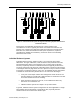
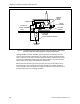
Table Of Contents
- About this Application Guide
- Chapter 1–Introduction
- Chapter 2–Goals of the Laboratory Environment
- Chapter 3–Unique Ventilation Needs of a Laboratory Facility
- Chapter 4–Ventilation Systems Classification
- Chapter 5–Laboratory Facility Exhaust Systems
- Chapter 6–Laboratory Containment Units - Ventilation
- Chapter 7–Room Ventilation, Makeup Air, and Pressurization Control Systems
- Chapter 8–Laboratory Temperature and Humidity Control Systems
- Chapter 9–Laboratory Emergencies - Ventilation System Response
- Chapter 10–Laboratory Ventilation System - Validation
- Chapter 11–Laboratory Ventilation System - Commissioning
- Glossary
- Index

Chapter 5–Laboratory Facility Exhaust Systems
The control arrangement of Figure 5 includes other control devices and provisions
that are necessary to ensure proper and reliable operation for the overall exhaust
system. Each exhaust fan has an airflow proof switch to provide positive feedback of
the fan’s operation for system monitoring purposes and to enable automatic
activation of a standby fan (not shown in the diagram) in case of an operating fan
failure. Each fan is also equipped with leakage rated isolation dampers that
automatically open when the fan is started and automatically close if the fan is shut
down or fails. This ensures against airflow short circuiting whereby air would circulate
through an inoperative fan and reduce the effectiveness of the fan or fans that
remains in operation. These isolation dampers also allow maintenance personnel to
service a fan without being exposed to the exhaust air.
One Position CAV System Applications
When the system, shown in Figure 5, is applied to a laboratory facility served by a
simple one position constant volume ventilation system, the near constant level of
airflow always maintained through the facility ventilation system limits the need for
much variation in the amount of outside bypass air required. In such applications, the
bypass damper and static pressure control arrangement is still highly advised, but
the bypass damper can be relatively small in relation to the size of the main duct
entering the exhaust fan plenum.
Two Position CAV System Applications
When the type of exhaust system configuration, shown in Figure 5, is applied to
serve a facility that uses two position constant air volume systems, the bypass
damper will need to sufficiently large (approximately 1/4 the area of the main vertical
duct entering the exhaust plenum) to allow more outside air to enter the exhaust
plenum when the facility is unoccupied and less exhaust air is required. As an
alternative, the control system can also be arranged to shut off a fan to attain the
reduced airflow during the unoccupied period.
The drawback of shutting off a fan would, of course, be the lack of continuity of
exhaust system airflow if there was a single remaining exhaust fan running and it had
an operational failure. The consequences of a loss of all exhaust airflow should be
weighted against the potential hazard of such an occurrence in what would probably
be an unoccupied facility. For facilities that do not typically utilize hazardous
substances such as undergraduate college labs, this may not pose a significant
hazard. Research facilities that may utilize very toxic chemicals or substances of
course would be substantially affected by a total loss of exhaust system airflow.
VAV Applications
When the type of exhaust system configuration, shown in Figure 5, is applied to
serve a facility with variable air volume ventilation systems, the bypass damper must
be approximately 1/4 the area of the main vertical duct entering the exhaust plenum.
This will allow enough outside air to enter the exhaust plenum when there is
minimum demand on the exhaust system. As less demand is made on the exhaust
system, the bypass damper is modulated to allow more outside air into the exhaust
plenum; thus, maintaining the negative system static pressure at the desired level. As
more demand is made on the exhaust system (more fume hoods have their sashes
open), the bypass damper is modulated toward the closed position to enable drawing
more exhaust air from the facility.
28 Siemens Building Technologies, Inc.