
Basic Documentation
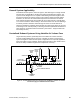
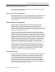
Table Of Contents
- About this Application Guide
- Chapter 1–Introduction
- Chapter 2–Goals of the Laboratory Environment
- Chapter 3–Unique Ventilation Needs of a Laboratory Facility
- Chapter 4–Ventilation Systems Classification
- Chapter 5–Laboratory Facility Exhaust Systems
- Chapter 6–Laboratory Containment Units - Ventilation
- Chapter 7–Room Ventilation, Makeup Air, and Pressurization Control Systems
- Chapter 8–Laboratory Temperature and Humidity Control Systems
- Chapter 9–Laboratory Emergencies - Ventilation System Response
- Chapter 10–Laboratory Ventilation System - Validation
- Chapter 11–Laboratory Ventilation System - Commissioning
- Glossary
- Index

Chapter 5–Laboratory Facility Exhaust Systems
Figure 6 shows a large centralized variable air volume exhaust system utilizing
individual VAV exhaust fans with individual stacks for each fan. The fans shown are
conventional centrifugal type that discharge through a vertical stack. As an option,
the fans may be comprised of special laboratory axial exhaust fans designed to
entrain large amounts of outside air and discharge the combination upwards at a
high velocity thus eliminating the need for a tall stack. Figure 6 also shows a static
pressure control arrangement for the exhaust system much like that of Figure 5.
The minimum operational configuration for Figure 6 normally consists of one or two
fans always running at a speed that ensures maintaining the minimum desired stack
exit velocity. When there is a need for more exhaust airflow from within the facility,
the system static pressure will tend to decrease (become less negative) and the
control arrangement will reduce the bypass damper opening to increase negative
static pressure (suction) throughout the system. Conversely, when there is less need
for exhaust airflow from within the facility, the system static pressure will tend to
increase (become more negative) and the control arrangement will increase the
bypass damper opening to reduce the negative static pressure (suction) throughout
the system.
Because of the bypass damper arrangement, the total airflow through the fans
remains relatively constant and the stack exist velocity remains relatively constant. If
more exhaust capacity is required by the facility than can be achieved by modulating
the bypass damper near the fully closed position, the fan(s) that are running are
speeded up. As still more exhaust capacity is required, additional fans are started by
the controller which then also equalizes the speed of all fans.
In the case of maximum facility demand on the exhaust system, all fans can be on at
near maximum speed while the bypass damper is nearly closed. With minimal
demand (that is, during unoccupied times) one fan may be running at minimum
speed and the bypass damper would be modulated to maintain the static pressure
level required. This arrangement provides maximum exhaust system flexibility as well
as maximum operational energy savings.
The centralized variable air volume exhaust system of Figure 6 also incorporates
isolation dampers between each exhaust fan and its inlet. The isolation dampers are
closed tightly when their respective fan is not running to ensure against drawing
outside air into the exhaust plenum through the non-operating fan. The isolation
dampers also allow preventive or remedial maintenance on a fan without exposing
maintenance workers to the exhaust air stream. The isolation dampers may be of the
barometric type in mild climates; however, motorized isolation dampers are
recommended in areas subject to freezing temperatures since freezing of
accumulated condensation on a barometric damper would make the damper
inoperable.
Aside from using conventional centrifugal fans and exhaust stacks, the fans may be
comprised of special laboratory axial exhaust fans designed to entrain large amounts
of outside air and discharge the combination upwards at a high velocity thus
eliminating the need for tall stacks. Such types of fans are generally interchangeable
with the centrifugal fans shown in Figure 6; however, the basic control remains much
the same.
30 Siemens Building Technologies, Inc.