
Basic Documentation
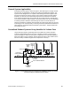
Table Of Contents
- About this Application Guide
- Chapter 1–Introduction
- Chapter 2–Goals of the Laboratory Environment
- Chapter 3–Unique Ventilation Needs of a Laboratory Facility
- Chapter 4–Ventilation Systems Classification
- Chapter 5–Laboratory Facility Exhaust Systems
- Chapter 6–Laboratory Containment Units - Ventilation
- Chapter 7–Room Ventilation, Makeup Air, and Pressurization Control Systems
- Chapter 8–Laboratory Temperature and Humidity Control Systems
- Chapter 9–Laboratory Emergencies - Ventilation System Response
- Chapter 10–Laboratory Ventilation System - Validation
- Chapter 11–Laboratory Ventilation System - Commissioning
- Glossary
- Index

Laboratory Exhaust Systems - General Requirements
FRP (Fiberglass Reinforced Polyester)
This is a very good all around duct material due to its resistance to most chemicals
and its ability to withstand vibration.
Epoxy and Teflon
®
Coated Materials
Although these materials have excellent chemical resistivity, it is very difficult to apply
them in a manner which forms a very thorough covering without any breaks or
seams. Experience has shown that where a break or junction is present in a Teflon
®
covering, this location becomes most prone to corrosion since it tends to trap
chemical residues.
Exhaust System Configuration
Laboratory exhaust systems should be carefully designed and configured for
maximum efficiency, adequate transport velocities, low pressure loss and an
acceptable noise level. Exhaust systems should also include provisions for
inspection, monitoring and servicing. Although the scope of these requirements is too
extensive to be thoroughly covered within this section, the key points to consider are
listed with some pertinent commentary.
Laboratory exhaust ductwork should preferably be round rather than rectangular.
Ductwork sections must be joined in a manner that makes them structurally sound
and relatively airtight. For stainless steel, this normally involves welding each section
together. The objective of the installation is to approach that of a single smooth pipe.
If galvanized sheet metal ductwork is utilized, the connections should be by means of
slip type joints and all joints should be thoroughly sealed with a high quality silicone
sealant. The most crucial element of the entire exhaust system is the quality of its
installation and fabrication. Regardless of how well the system is designed or how
well suited the material selected may be, the quality of on-site workmanship
(especially the joint construction) typically determines the service life of the system.
Changes in duct sizes after junctions should utilize gradual transition sections.
Changes in direction should utilize wide radius types of fittings. Conventional 90°
segmented elbows, tees, and similar fittings that introduce appreciable turbulence
and friction are not acceptable.) The use of flexible duct anywhere in a laboratory
exhaust system should always be avoided because its internal surface allows
particulate to collect and it is susceptible to physical damage.
Transport Velocity
Exhaust system ducts should be sized for nominal transport velocities (air speeds) of
1,000 to 2,000 feet per minute (fpm) to ensure against settling of particulate and
minimizing the likelihood of condensation of vapors within the exhaust system.
Velocities below 500 fpm should be especially avoided since this also prevents
accurate flow measurements which is necessary for precise testing, balancing,
commissioning and control. Airflow velocities over 3,000 fpm within a building’s
interior should be avoided since this will result in inefficient system operation which
will increase fan electrical energy costs. In addition, such high airflow velocities will
likely generate an objectionable high sound level.
Siemens Building Technologies, Inc. 37