
Basic Documentation


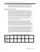
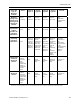
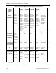
Table Of Contents
- About this Application Guide
- Chapter 1–Introduction
- Chapter 2–Goals of the Laboratory Environment
- Chapter 3–Unique Ventilation Needs of a Laboratory Facility
- Chapter 4–Ventilation Systems Classification
- Chapter 5–Laboratory Facility Exhaust Systems
- Chapter 6–Laboratory Containment Units - Ventilation
- Chapter 7–Room Ventilation, Makeup Air, and Pressurization Control Systems
- Chapter 8–Laboratory Temperature and Humidity Control Systems
- Chapter 9–Laboratory Emergencies - Ventilation System Response
- Chapter 10–Laboratory Ventilation System - Validation
- Chapter 11–Laboratory Ventilation System - Commissioning
- Glossary
- Index

Containment Units
Average face velocities appreciably exceeding 100 fpm have been found to create
turbulence and a “rolling effect” within the fume hood interior and sometimes right at
the sash opening. This can result in fumes being carried out through portions of the
face opening of the fume hood. Similarly an average face velocity significantly below
100 fpm does not normally provide very effective containment.
It is important to note again that having a 100 fpm fume average fume hood face
velocity does not guarantee fume containment and protection for the user. Other
factors such as room air cross currents that exceed about 50% of the average face
velocity at the sash opening can adversely affect fume hood containment. Such
factors are usually caused by utilizing incorrect supply air diffusers for a chemical
laboratory application, diffusers that are located too close to a fume hood or diffusers
located on side walls. More details on these factors will be provided later in this
document.
Ventilation for Chemical Fume Hoods
The various types of chemical fume hoods described previously can also be
categorized based upon their ventilation system arrangement into several types:
• Constant volume fume hoods–This is perhaps the most common type of
fume hood exhaust arrangement in use today. As its name infers, it operates
in conjunction with a constant air volume ventilation system whereby the total
air being exhausted from the fume hood remains relatively constant
regardless of the size of face opening or sash configuration. All of various
physical configurations of fume hoods described, including the bench, walk-
in, distillation, perchloric acid and radioisotope, are available for use with
constant volume ventilation systems. Some of these fume hoods, (the
perchloric acid and radioisotope especially) should only be used with a
constant volume exhaust provision.
• Constant volume bypass fume hoods–Bench top fume hoods in particular
and certain other types can also be arranged with a self regulating feature
called a bypass area. In addition to the makeup air that enters through the
open sash area, a constant volume bypass fume hood also allows makeup
air to enter through a “bypass” opening that varies in size as the sash is
opened or closed. The bypass opening is intended to provide an alternate
open area for the makeup air to flow into the fume hood when the sash is not
fully open. Thus, as the fume hood sash is moved from fully open toward the
fully closed position, the sash uncovers an almost equivalent bypass area
that keeps the fume hood’s total open area (open face areas and uncovered
bypass area) nearly the same for all sash positions. This is intended to
prevent the air that enters through the open sash area from appreciably
increasing in velocity. Figure 7 illustrates how a constant volume bypass
fume hood with a vertical sash maintains a nearly constant face velocity and
exhaust rate regardless of the sash position.
Siemens Building Technologies, Inc. 47