
Basic Documentation
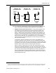
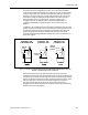
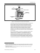
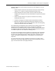
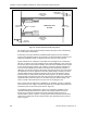
Table Of Contents
- About this Application Guide
- Chapter 1–Introduction
- Chapter 2–Goals of the Laboratory Environment
- Chapter 3–Unique Ventilation Needs of a Laboratory Facility
- Chapter 4–Ventilation Systems Classification
- Chapter 5–Laboratory Facility Exhaust Systems
- Chapter 6–Laboratory Containment Units - Ventilation
- Chapter 7–Room Ventilation, Makeup Air, and Pressurization Control Systems
- Chapter 8–Laboratory Temperature and Humidity Control Systems
- Chapter 9–Laboratory Emergencies - Ventilation System Response
- Chapter 10–Laboratory Ventilation System - Validation
- Chapter 11–Laboratory Ventilation System - Commissioning
- Glossary
- Index

Containment Units
With reference to the arrangement of Figure 9, the fume hood controller
continuously monitors the movable sash position by means of sash position
sensors. This enables the controller to calculate the sash open area (face
opening) of the fume hood. For a single vertical opening sash, the vertical
sash travel is simply multiplied by the fixed width of the sash opening to
obtain the open face area in square feet. For more complex sash
arrangements such as multiple sashes, horizontal sliding sashes, or
combination horizontal and vertical sashes, several sash sensors are
applied.
In addition to the variable open face area which is dependent upon the sash
position, all fume hoods also have a certain amount of fixed open area such
as that which is below the airfoil. Therefore, the total open area of a fume
hood at any given point in time is determined by the VAV Fume Hood
Controller mathematically adding the variable open face area and the fixed
open area together.
@ MAXIMUM CFM @ APPROX. 50% @ APPROX. 20%
EXHAUST AIR
100% OPEN
50% OPEN CLOSED
BYPASS
AREA
MOVABLE
SASH
AIRFLOW
CONTROL
ELEMENT
EXHAUST AIR EXHAUST AIR
SASH SASH SASH
SASH SASH SASH
Figure 8. Variable Air Volume (VAV) Fume Hood Showing the Reduction in Exhaust
Airflow as the Sash Open Area is Reduced.
With the total open area of the fume hood calculated, the fume hood
controller next determines the required fume hood exhaust by multiplying the
total open area in square feet times the desired face velocity feet per minute
(FPM). The product of these two factors yields the required exhaust in cubic
feet per minute (cfm). The fume hood control arrangement in Figure 9
maintains this exhaust airflow rate by an active closed loop control
arrangement that utilizes an airflow measurement sensor and a modulating
damper in the fume hood exhaust.
Siemens Building Technologies, Inc. 51