
Basic Documentation
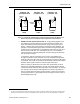
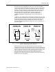
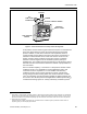
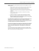
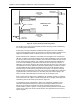
Table Of Contents
- About this Application Guide
- Chapter 1–Introduction
- Chapter 2–Goals of the Laboratory Environment
- Chapter 3–Unique Ventilation Needs of a Laboratory Facility
- Chapter 4–Ventilation Systems Classification
- Chapter 5–Laboratory Facility Exhaust Systems
- Chapter 6–Laboratory Containment Units - Ventilation
- Chapter 7–Room Ventilation, Makeup Air, and Pressurization Control Systems
- Chapter 8–Laboratory Temperature and Humidity Control Systems
- Chapter 9–Laboratory Emergencies - Ventilation System Response
- Chapter 10–Laboratory Ventilation System - Validation
- Chapter 11–Laboratory Ventilation System - Commissioning
- Glossary
- Index

Chapter 7–Room Ventilation, Makeup Air, and Pressurization Control Systems
PERSONNEL
CORRIDOR
SERVICE
CORRIDOR
ADJACENT
LABORATORY
ROOM
ADJACENT
LABORATORY
ROOM
LABORATORY
ROOM
FUME HOOD
FUME HOOD
CHEMICAL
STORAGE
CHEMICAL
STORAGE
GAS CYLINDERS
SECONDARY
ENTRY / EXIT
PRIMARY
ENTRY / EXIT
Figure 10. Proper Laboratory Room Arrangement.
The location of the room general exhaust provisions also plays a role in maximizing
the overall system effectiveness.
A laboratory room layout should be established with regard to how the ventilation
system can be applied to protect the occupants. The most hazardous operations and
equipment should be located at a distance from the main room entry and exit.
Figure 10 illustrates an example of a desirable room arrangement for a smaller size
lab room. It shows a two person modular type of chemical laboratory room of the type
that is often used in new research facilities. The fume hood containment units as well
as the chemical storage cabinets, gas cylinders, and other hazardous equipment is
at the end of the laboratory room that is most distant from the primary entry/exit. A
laboratory room service corridor is also shown along this end of the room. This layout
encompasses the current approach to laboratory facility design, whereby the service
corridor enables moving hazardous materials into and out of the laboratory rooms
without having to use the primary entry/exit for this purpose. The primary entry/exit
allows entering and exiting the room away from the more hazardous area. Aside from
regular laboratory service functions, the secondary entry/exit shown leading to the
service corridor is also intended to serve the room as an emergency exit.
After a proper room arrangement is established, the ventilation system is configured
to best serve the room. Figure 11 shows the proper way to arrange a laboratory room
ventilation system for the room layout shown in Figure 10.
The ventilation system arrangement in Figure 11 is intended to establish a room
ventilation airflow pattern that moves room air from supply air diffusers near the
primary entry toward the chemical fume hoods and other potential sources of
chemical fumes, vapors or gasses. A room general exhaust provision has also been
located in the ceiling near the fume hoods and the other potential sources of fumes,
vapors or gases.
58 Siemens Building Technologies, Inc.