
Basic Documentation
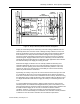
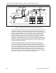
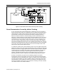
Table Of Contents
- About this Application Guide
- Chapter 1–Introduction
- Chapter 2–Goals of the Laboratory Environment
- Chapter 3–Unique Ventilation Needs of a Laboratory Facility
- Chapter 4–Ventilation Systems Classification
- Chapter 5–Laboratory Facility Exhaust Systems
- Chapter 6–Laboratory Containment Units - Ventilation
- Chapter 7–Room Ventilation, Makeup Air, and Pressurization Control Systems
- Chapter 8–Laboratory Temperature and Humidity Control Systems
- Chapter 9–Laboratory Emergencies - Ventilation System Response
- Chapter 10–Laboratory Ventilation System - Validation
- Chapter 11–Laboratory Ventilation System - Commissioning
- Glossary
- Index

Chapter 7–Room Ventilation, Makeup Air, and Pressurization Control Systems
The fume hoods or biosafety cabinets may not effectively remove all fumes, vapors
and gasses that may be released into the laboratory room itself. A room general
exhaust located right above where the area where fume release might occur (near the
chemical storage cabinets, gas cylinders, etc.).
Since fumes and gasses released in chemical laboratories can be buoyant, the
general exhaust is most effective when located on the ceiling to help remove fumes,
gasses, vapors, or smoke released within the room. It is also very important to locate
the ceiling general exhaust sufficiently distant from the supply air diffusers to prevent
short circuiting the room airflow. Short circuiting occurs when a portion of the
incoming supply air is immediately drawn into the room general exhaust before the
supply air can effectively diffuse and provide effective ventilation for the room.
In contrast to chemical laboratories, organic chemical vapors that are often present in
biological laboratories are much heavier than air and therefore tend to sink to the
floor. Therefore in biological laboratories, it is recommended that one or more
general room exhausts be provided and located near the floor level, close to the
biological safety cabinets, to remove such vapors.
When providing a room general exhaust, the exhaust capacity with respect to the
room floor area should be at least 0.5 cfm per square foot (2.5 l/s per square meter)
to be effective in removing fumes that rise to the ceiling level.
Room Environmental Modeling
Where documented assurance is needed that the airflow pattern within a room will
not adversely affect the performance of the room’s containment units, or where a
detailed analysis of the room would help solve an existing environmental problem,
mathematical analysis techniques for accurate graphical depictions of room
dynamics can be applied. Room environmental modeling based upon computational
fluid dynamics (CFD) provides such a visual depiction of room air quality, airflow
velocity and distribution, room temperature distribution, and other factor related to the
room environment.
Room environmental modeling is a specialized service whereby the provider enters
all pertinent room data into a computer program that will process the data and create
plots of the resultant airflow at different planes in the room. The process also can
provide three dimensional color-coded animation of the room environment. The room
data that the process requires includes:
• Room geometry and dimensions
• Dimensions and position of all furniture and major equipment
• Location and type of all air supply diffusers and exhaust grills and their
volumetric airflow
• Location of heat producing equipment including lighting
• Location of the room occupants (optional)
60 Siemens Building Technologies, Inc.