
Basic Documentation
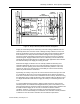

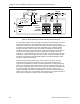
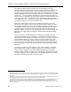
Table Of Contents
- About this Application Guide
- Chapter 1–Introduction
- Chapter 2–Goals of the Laboratory Environment
- Chapter 3–Unique Ventilation Needs of a Laboratory Facility
- Chapter 4–Ventilation Systems Classification
- Chapter 5–Laboratory Facility Exhaust Systems
- Chapter 6–Laboratory Containment Units - Ventilation
- Chapter 7–Room Ventilation, Makeup Air, and Pressurization Control Systems
- Chapter 8–Laboratory Temperature and Humidity Control Systems
- Chapter 9–Laboratory Emergencies - Ventilation System Response
- Chapter 10–Laboratory Ventilation System - Validation
- Chapter 11–Laboratory Ventilation System - Commissioning
- Glossary
- Index

Chapter 7–Room Ventilation, Makeup Air, and Pressurization Control Systems
CFM
CFM
SUPPLY TERMINAL
ROOM
CONTROLLER
DIFFERENTIAL
PRESSURE
SENSOR
P
CONSTANT
VOLUME
FUME HOODS
ROOM
GENERAL
EXHAUST
EXHAUST
Figure 12. Room Static Pressurization Control by Pressure Sensing.
The potential problem with door openings can however be addressed by the control
arrangement in Figure 12 which adds airflow measurement to the room supply
airflow. This enables the room controller to maintain a preset minimum supply airflow
rate when room pressurization cannot be maintained. Lastly, ventilation system
designers should be aware that since the airflow into laboratory rooms will vary
especially as doors are opened and closed, it will create somewhat of a problem to
ensure that the adjacent spaces (mostly corridors) have the proper amount of
makeup air. If several laboratory room doors are open, the corridor must have more
makeup air. If all doors are closed, less air is needed. Therefore ventilation system
designers must anticipate these potential problems and include adequate control
scenarios to address these issues.
Aside from maintaining control over the static pressure of the room, the room
controller must also ensure that sufficient air is being provided to maintain the
required room ventilation rate which is normally expressed in air changes per hour
(ACH). The constant air volume fume hoods in the room exhaust a fixed volume of
air; however, depending upon the size of the room and total exhaust provisions, this
may not be enough to maintain the required room ACH rate. In Figure 12, the
required additional room exhaust is attained by the room general exhaust provision
located in the ceiling. The room controller also controls the room general exhaust to
always ensure that there is sufficient total room exhaust airflow.
66 Siemens Building Technologies, Inc.