
Basic Documentation
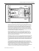
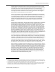
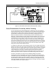
Table Of Contents
- About this Application Guide
- Chapter 1–Introduction
- Chapter 2–Goals of the Laboratory Environment
- Chapter 3–Unique Ventilation Needs of a Laboratory Facility
- Chapter 4–Ventilation Systems Classification
- Chapter 5–Laboratory Facility Exhaust Systems
- Chapter 6–Laboratory Containment Units - Ventilation
- Chapter 7–Room Ventilation, Makeup Air, and Pressurization Control Systems
- Chapter 8–Laboratory Temperature and Humidity Control Systems
- Chapter 9–Laboratory Emergencies - Ventilation System Response
- Chapter 10–Laboratory Ventilation System - Validation
- Chapter 11–Laboratory Ventilation System - Commissioning
- Glossary
- Index

Laboratory Room Pressurization
CFM
SUPPLY TERMINAL
ROOM
CONTROLLER
VARIABLE
VOLUME
FUME HOODS
EXHAUST
ROOM
GENERAL
EXHAUST
FUME HOOD
CONTROLLERS
CFM
CFM
CFM
Figure 13. Room Static Pressurization Control by Airflow Tracking.
Room Pressurization Control by Airflow Tracking
A more commonly used and preferable means to maintain a room at a negative or
positive pressure with respect to an adjoining area is by airflow tracking (sometimes
called volumetric airflow tracking). Whereas the pressure sensing method of room
pressurization control (Figure 12) is based upon directly sensing the pressure
difference between two spaces, airflow tracking consists of maintaining a fixed
difference or offset between the room supply and exhaust airflows. For a room to be
negatively pressurized, airflow tracking control ensures that the total amount of air
exhausted from the room always exceeds the amount of air that is supplied to the
room. The creates a slight vacuum effect in the room which causes air in adjacent
areas to flow towards and into the room. For a positively pressurized room, the total
amount of air exhausted from the room is less than the amount of air that is supplied
to the room. The creates an excess amount of air in the room which tends to flow
away from the room and into adjacent areas.
In variable air volume (VAV) room ventilation systems, the room supply and exhaust
airflows are varied to meet the needs of the laboratory room. However, the difference
between the total room supply airflow and the total room exhaust airflow is controlled
to always remain at a constant value. Figure 13 shows a laboratory room with the
control components necessary to achieve negative static pressure by airflow
tracking. The difference between Figure 12 and Figure 13 is that, in Figure 13, no
differential pressure sensor is required for the airflow tracking method of control.
As before, the laboratory in Figure 13 has modulating dampers and airflow
measurement sensors in the supply air and in the room general exhaust which are
controlled by the room controller just as in Figure 12. Aside from the room supply air
and room general exhaust, the room controller of Figure 12 also keeps track of the
exhaust airflow of each variable air volume fume hood by the cfm signals that each
fume hood controller provides to the room controller. In this way, the room controller
can totalize all of the room exhaust airflows.
Siemens Building Technologies, Inc. 67